Get in touch with AQUA Company

Updated September 2026
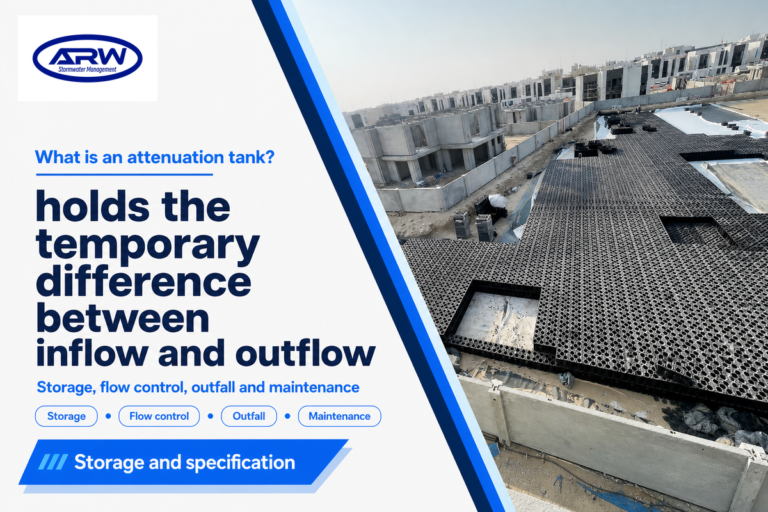
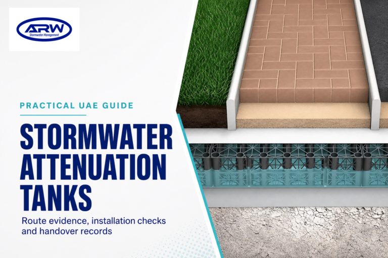
Geocellular attenuation tanks are lined, below-ground tanks designed to hold and release stormwater through a controlled outlet. The cells of a system are just one part of the design. The other parts include inlets, an impermeable envelope, pipe connections, flow control, overflow, access for inspection, backfill, and surrounding soil. The complete system must be considered in order to fulfill the desired design intent.
This guide allows designers, contractors, developers, and buyers to establish the requirements for product selection based on the interfaces of those products. It does not replace the hydraulic, structural, geotechnical or regulatory work required for a project. Local rules and the qualified project team remain the authority for the final design.
Key takeaway
Choose a geocellular module only after the project team has defined the water route, storage basis, loads, interfaces, access and evidence needed for the complete installed system.
What a Geocellular Attenuation Tank Does
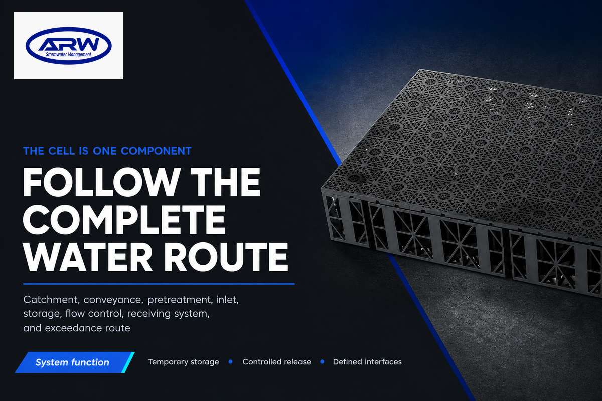
Runoff flows through the catchment, conveyance, and pretreatment systems to reach the underground storage system during a rainfall event. The tank holds the calculated volume, then the outlet control releases water to the receiving system at the agreed rate. Outside of design flows, flows are managed by an exceedance route.
On a new development, the tank may sit within a wider surface water management system. Rainwater can pass through source controls, a swale, pond, silt traps or another treatment feature before it reaches the buried storage and downstream drain. Sustainable drainage systems, often shortened to SuDS in some markets, work best when each component has a stated function. “Crate” is common shorthand for a cell, but it isn’t a technical specification for material, load grade, geometry or connection detail. In stormwater management, geocellular systems are components within larger stormwater systems. Their modular design does not remove the need for an installation process that coordinates the cells, lining, pipework, controls and groundworks.
The sequence is as follows: catchment, conveyance, pretreatment, inlet, modular storage, flow control, receiving system and exceedance route. If there’s a failure on any of the interfaces, then system performance is likely to vary. Inlet blockages reduce the available capacity. Sub-optimal outlets can change drawdown. Poor backfill or assembly can compromise structural behaviour. Inaccessible controls impede inspection and cleaning.
This is the reason a cell supplier can provide product geometry and bounded test information without becoming the project drainage designer. The susDrain geocellular storage guidance treats storage, pretreatment and maintenance as integral parts of drainage systems.
Attenuation, Infiltration and Reuse Are Different Briefs
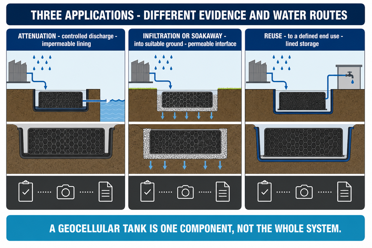
These three applications can use modular storage, but they require different forms of evidence and water routes. Calling every underground cell structure an attenuation tank hides decisions that need to be made at the outset. Market language also overlaps: geocellular crates may be sold as attenuation crates for controlled discharge or as soakaway crates and soakaway tanks for infiltration. Rainwater harvesting systems add a separate reuse brief.
Decision rule: A geocellular tank is one component, not the whole system. An attenuation tank vs soakaway comparison starts with the water route; attenuation tank design then assigns storage, outlet, loads, access and maintenance.
| Application | Water route | Containment concept | Extra evidence |
|---|---|---|---|
| Attenuation | Controlled discharge | Impermeable lining | Allowable discharge, outlet and exceedance basis |
| Infiltration or soakaway | Into suitable ground | Permeable interface | Field infiltration, groundwater and environmental assessment |
| Reuse | To a defined end use | Lined storage | Treatment, pumps, controls and end-use quality |
A permeability value isn’t sufficient for an infiltration proposal. The team should evaluate seasonal groundwater, past use of the land, the potential migration of contaminants, wells, foundations, and sensitive receptors. Field conditions, soil preparation and clogging risk will also be important to consider. The University of Minnesota stormwater guidance describes the impact that site selection, field testing, compaction, and maintenance of a site can have on the performance of infiltration.
Making a non-permeable wrap permeable still wouldn’t transform an unsuitable site into a safe soakaway. If depth is the main constraint, check the available envelope and project duties and evaluate a shallow attenuation drainage approach.
Define the Hydraulic Brief Before Choosing Modules
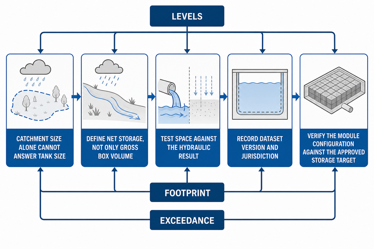
The answer to “What size tank do I need?” isn’t straightforward from catchment size alone. The project designer needs the data for the selected rainfall event, assumptions on runoff, the inflow profile, the allowed discharge or infiltration basis, the route of the outflow, levels, available footprint, the condition of exceedance, and the approach required by the relevant authority.
These inputs define net storage rather than only a gross box volume. Selection of pipework, access methods, unusable zones and confirmed module geometry defines how a storage target becomes a configuration. The outlet and its drawdown effect matter also. A different allowable discharge can change the hydrograph defining the volume required. For stormwater attenuation, the brief links surface water runoff and heavy rainfall inputs to water storage, inlet and outlet pipes, and controlled release.
Leave clear records that others can understand and follow. The brief should include catchment boundaries, surface types, rainfall source, event criteria, the method of runoff, initial water level, the basis of inflow and outflow, the destination of discharge, any allowance for climate or authority, and any calculations/drawings done with a consistent level datum.
Illustrative input register: The fictional values below show how units can be recorded. They are not design recommendations, calculations or AQUA product ratings; replace every entry with project evidence.
| Record | Illustrative value | Decision use | Source / reference |
|---|---|---|---|
| Rainfall basis | 75 mm over 6 hours; 10 years | Define the selected event | Local rainfall dataset |
| Inflow result | 18 m³/hour; 420 m³ over 2 hours | Record model output | Hydraulic model |
| Outlet basis | 12 m³/hour; 24 hours | Check controlled release | Discharge consent |
| Available envelope | 0.8 m cover; 2.4 m base | Test layout constraints | Plan and section |
| Groundwater record | 1.0 m separation; 3.2 m datum | Check uplift and infiltration | Ground investigation |
| Load case | 45 kN axle; 120 kPa pressure | Define structural checks | Structural brief |
| Backfill control | 150 mm lifts; 95% density | Record construction control | Construction specification |
| Pretreatment detail | 2 mm screen; 0.5 m sump | Assign sediment control | Treatment plan |
| Inspection timing | 3 months; 12 months | Set initial review points | Operations plan |
If the receiving connection or the discharge consent is still provisional, mark it as an open dependency, as opposed to hiding it inside a final looking storage figure.
Space constraints should be tested against the hydraulic result, not used to force a preferred tank size. Should the volume not fit, then the design team may have to revisit some of the source control, levels, footprint, discharge terms or other areas of the drainage system concept. The product supplier can test their building blocks against the approved storage target, but shouldn’t change the hydrology of the project in order to accommodate their preferred layout of modules.
Rainfall references also need a version and jurisdiction. In the United States, for example, the National Oceanic and Atmospheric Administration says Atlas 15 is under development, while Atlas 14 remains current until the new publication is issued. That transition isn’t a universal design instruction. It’s a reminder to record exactly which dataset and version govern each project.
Use the Six-Layer Attenuation Brief
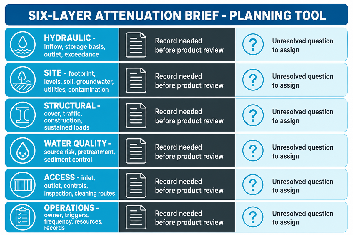
The Six-Layer Attenuation Brief is a planning tool within the AQUA framework and isn’t a standard or approval pathway. It consolidates linked decisions on a single page to identify gaps and inform configuration of a product.
| Layer | Record before product review | Unresolved question to assign |
|---|---|---|
| Hydraulic | Inflow, storage basis, outlet and exceedance | Who approves the calculation and discharge? |
| Site | Footprint, levels, soil, groundwater, utilities and contamination | Which surveys and field tests remain open? |
| Structural | Cover, traffic, construction and sustained loads | Who checks the installed system? |
| Water quality | Source risk, pretreatment and sediment control | What treatment duty applies locally? |
| Access | Inlet, outlet, controls, inspection and cleaning routes | Can each maintainable asset be reached safely? |
| Operations | Owner, triggers, frequency, resources and records | Who acts when inspection finds a problem? |
A buyer can send this table to the drainage designer, the civil contractor, and facilities before requesting prices. This helps pinpoint gaps and reduces the chance that one party assumes the gap is owned by another.
Storage Capacity Is Not a Treatment Credit
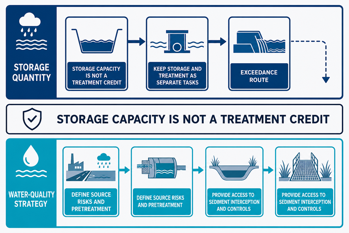
A high void ratio reflects the storage capacity, however, it doesn’t warrant a water-quality treatment credit. Some suspended material may settle while runoff is held, but incidental settling does not replace the pretreatment or treatment train required for the catchment and jurisdiction.
The United States Environmental Protection Agency fact sheet on underground detention describes these systems primarily as quantity controls and does not assign them a specific water-quality design function. The design consequence is simple: keep the storage calculation and the treatment strategy as two separate tasks.
Do
- Define source risks and pretreatment.
- Provide access to sediment interception and controls.
- Plan an exceedance route beyond the design event.
Don’t
- Treat storage volume as verified pollutant removal.
- Bury controls without an inspection route.
- Assume controlled discharge removes exceedance risk.
When the envelope must be separated, define layers by function and if filtration or protection is to be used, specify each layer. A selected geotextile should relate to the project detail and not substitute for the water-quality strategy.
Separate Product Test Data From Installed-System Approval
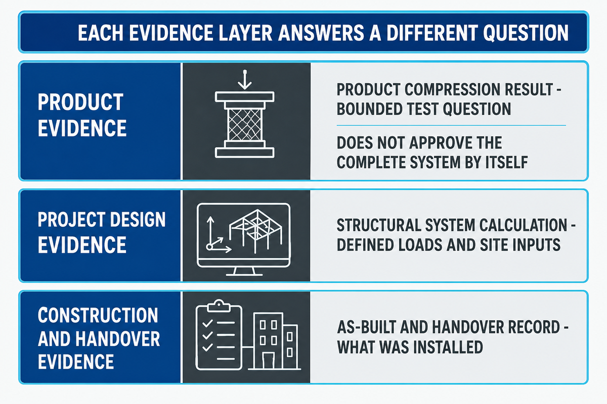
A product compression result answers a bounded test question, but it does not, by itself, approve the complete system below a road, car park, landscape or construction route. Structural review should consider permanent and transient loads, sustained loading and creep, cover, traffic, construction plant, soil and backfill, groundwater, connections, assembly and installation sequence.
| Evidence type | Question it can answer | What it cannot replace |
|---|---|---|
| Product geometry record | Which dimensions and supplied components apply | Usable system-volume assessment |
| Product compression test | How a specimen behaved under the stated test | Long-term project assessment |
| Material long-term evidence | How time-dependent behaviour was assessed | Site loads and construction detail |
| Hydraulic calculation | How inflow, outflow and storage were related | Structural suitability |
| Structural system calculation | How defined loads and site inputs were checked | Ground investigation |
| Geotechnical and groundwater report | Which ground and water conditions apply | Product performance data |
| Water-quality and access plan | How treatment, inspection and cleaning are assigned | Installation method |
| Construction-stage check | Whether temporary conditions match the method | Final handover records |
| As-built and handover record | What was installed and who operates it | Missing design evidence |
Units need to be included in the evidence pack in addition to values. A dimension entered as 500 should state whether it means 500 mm; a flow entered as 10 should state 10 L/s, and a load entered as 50 should state 50 kPa or 50 kN. These are example notations, not recommended project values.
Just because the modules are the highest grade available, this doesn’t mean it’s the most suitable option. It may still be compromised by an unsuitable foundation, cover, lateral restraint or construction method. For a trafficked area, the complete system should be reviewed on a project basis, as opposed to a general cover recommendation.
Use the Module-to-System Responsibility Map
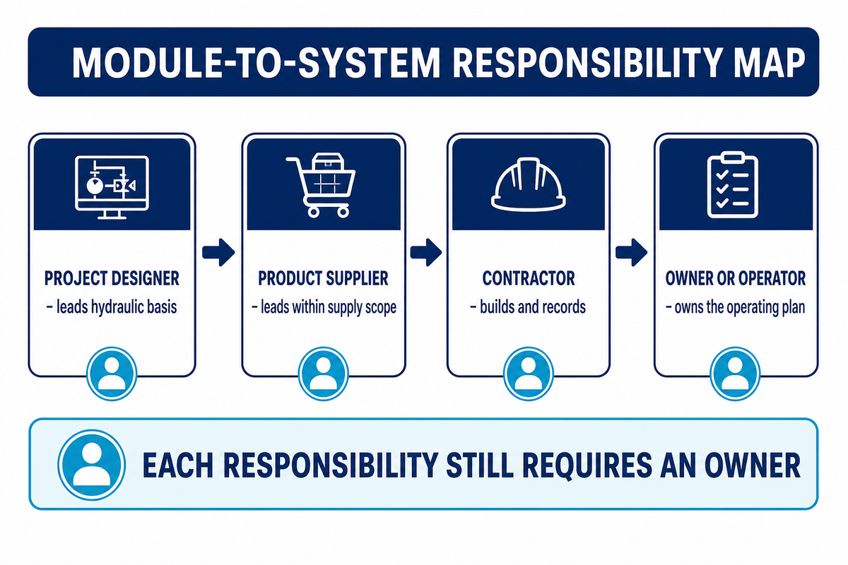
The Module-to-System Responsibility Map separates the supply of modules from the design, construction and operation of a system. Under contracts, names may change, but each responsibility still requires an owner.
| Decision or record | Project designer | Product supplier | Contractor | Owner or operator |
|---|---|---|---|---|
| Hydraulic and discharge basis | Leads | Supplies bounded inputs | Follows approved design | Accepts operating basis |
| Configuration and order records | Reviews | Leads within supply scope | Confirms constructability | Receives records |
| Base, wrap, connections and backfill | Specifies | Provides agreed guidance | Builds and records | Receives completion evidence |
| Inspection and maintenance plan | Defines performance needs | Provides product and access data | Builds accessible assets | Owns the operating plan |
AQUA supplies products, supporting materials, product-related documents, and agreed technical support. AQUA doesn’t claim to be the contractor for the installation of the project. This boundary enables the client to request evidence from each party, rather than expecting one product document to answer all project decisions.
Design Inspection and Maintenance Before Burial
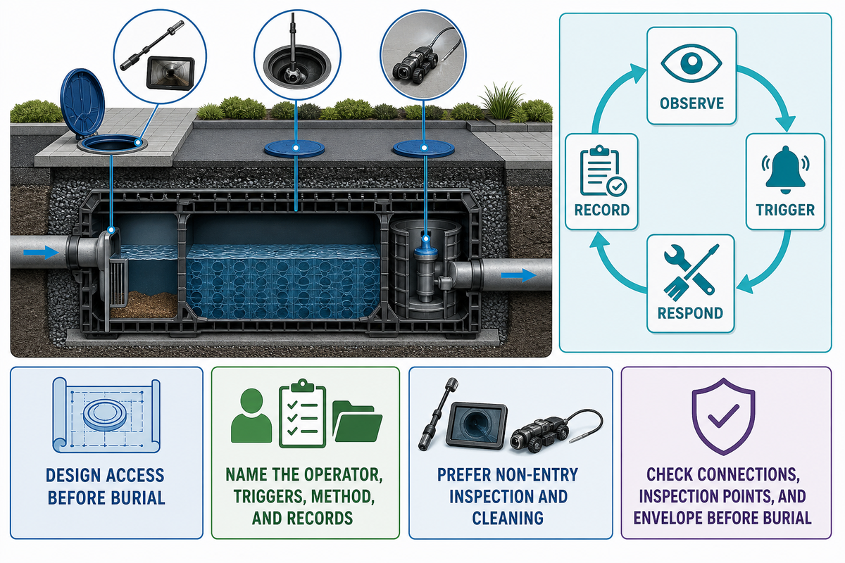
Maintenance access should be included in the design as it may be difficult to add this after the system has been buried. Identify points of pretreatment and sediment interception as well as inlets, outlets, flow control, inspection and cleaning paths on the design. Name the responsible operator, inspection triggers, intended method and records to retain.
The handover should include normal operating conditions and abnormal conditions, which either indicate a problem or trigger a response. The log should include an approved outlet setting, inspection locations, accessible pipeways, cleaning method, photographs prior to burial, and a space to note any findings. The operator also needs a route for escalating damage, persistent sediment, restricted discharge or unexpected standing water. A maintenance interval ‘copied’ from another project isn’t sufficient when the catchment, pollutant load and access scheme are all different.
Prefer non-entry inspection and cleaning where practicable. If a person can enter an underground access way, a competent party should assess the hazards and apply the local entry, monitoring, rescue and work-control provisions. The United States Occupational Safety and Health Administration considers sewers and pits as example confined spaces. It also states that flash flooding in storm sewers is a potential engulfment hazard. Other countries may have their own laws.
The service life of a component resists a single universal number. Material basis, sustained loads, ground and water conditions, joints, construction quality, access and maintenance all influence the assessment. A product warranty and an engineering design-life assessment are different documents.
Construction controls require the same attention. Heavy plant and stockpiles should be managed within the temporary load assumptions. Exposed materials should be protected. The formation should be monitored and the specified backfill sequence should be recorded. Prior to burying the system, the connections, inspection points and the envelope should be checked for continuity and any departures from the approved detail. Once the system is buried, evidence may be the only practical way to confirm what was installed.
Build a Burial-Ready Evidence Ladder
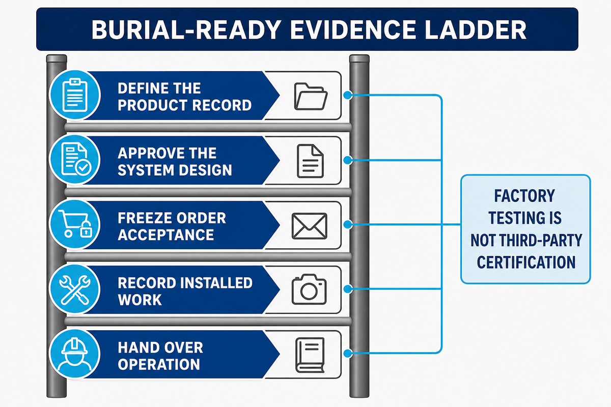
The Burial-Ready Evidence Ladder helps prevent a product certificate from being used in place of calculations, construction records, or an operating plan. Build the pack in sequential order, and ensure each layer is tied to its owner.
- Define the product record — capture dimensions, material, supplied components and the limits of test data.
- Approve the system design — retain the hydraulic, structural, geotechnical, water-quality and access work.
- Freeze order acceptance — agree the configuration, inspection plan, witness points and document schedule.
- Record installed work — document formation, wrap, connections, assembly, backfill and as-built changes.
- Hand over operation — confirm commissioning, triggers, maintenance ownership and retained records.
A factory sampling basis isn’t a statistically defined acceptance plan, independent assurance or third-party certification, and must be documented separately for moulded products and procured geotextiles, geomembranes and EPDM batches.
For those projects requiring witness testing or selected third-party reports, the requirement must be included in the order acceptance record. The same record should distinguish the inspection scope, sampling basis, witness points and required documents for each supplied component. Factory testing must not be labelled as third-party certification.
Use the 10-Question Pre-Specification Check
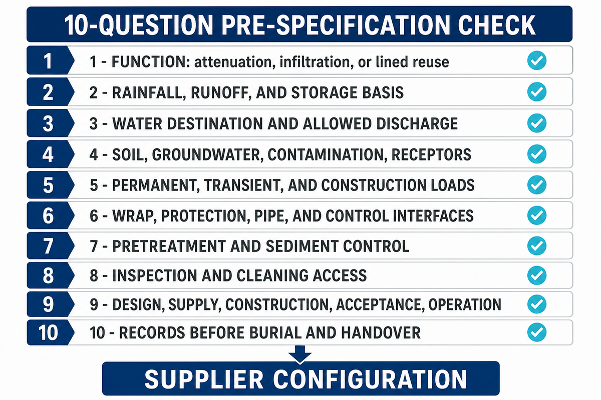
The 10-Question Pre-Specification Check is the last check the team does before asking the supplier to configure the modules. If an answer is still unknown, assign it to the responsible party and return to the project definition.
- Is the function attenuation, infiltration or lined storage for reuse?
- Which rainfall, runoff and storage basis governs?
- Where does water go, and what discharge rate is allowed?
- What do soil, groundwater, prior use, contamination and nearby receptors permit?
- Which permanent, transient and construction loads apply?
- Who defines the wrap, protection, pipe and control interfaces?
- What pretreatment and sediment control are required?
- Can every maintainable asset be inspected and cleaned?
- Who owns design, supply, construction, acceptance and operation?
- Which records must be accepted before burial and handover?
Move From a Defined Brief to Product Review
A supplier handover should include the function, the basis of storage, discharge or infiltration route, site conditions, loads, interface materials, treatment, access, required quantity, destination, and schedule. Once that neutral pack is complete, you may review AQUA geocellular stormwater tank configurations as a commercial product step. Model specifications, grade selection, quantity tools, packing, and quote will remain on that product page rather than being repeated here. For broader system context, review AQUA’s subsurface stormwater management overview; neither page replaces project-specific design or construction responsibilities. Where burial depth is the dominant constraint, compare the completed brief with AQUA’s shallow attenuation tank option only after the water route and responsibilities are fixed.
Owner-confirmed working capacity for the core moulded stormwater module range and annual export volume remain product-page evidence, not system-planning inputs. Buyers can also review AQUA’s product-support scope when assigning documents and witness points. For supplier identity and scope, see AQUA Rain Water’s company overview.
Request a Project-Input Review
Send the completed brief, site constraints, load cases and evidence list. AQUA can review product configuration and supply-scope questions without taking over the project designer’s or contractor’s duties.
Frequently Asked Questions
What is the purpose of an attenuation tank?
An attenuation tank temporarily stores stormwater during a rainfall event and releases it at a controlled rate. The cells create most of the storage space, but the liner, inlet, outlet control, overflow, access and surrounding construction complete the system. It is not automatically a credited treatment unit or an infiltration system.
How is an attenuation tank different from a soakaway?
An attenuation tank normally uses impermeable containment and a defined outlet. A soakaway uses a permeable interface so water can enter suitable ground. Infiltration requires evidence about soil, seasonal groundwater, prior land use, contamination, nearby wells, sensitive receptors and water quality. Field testing and maintenance access matter too. Changing the wrap alone does not make an unsuitable site safe for infiltration.
What size geocellular attenuation tank do I need?
A project designer needs the governing rainfall event or dataset, catchment boundaries, surface types, runoff assumptions, inflow profile, permitted discharge, receiving route, site levels, available footprint, exceedance condition and the method required by the local authority. Those inputs produce a net storage target. The team can then translate that target into a configuration using verified module geometry, void assumptions, pipework and access requirements. Catchment area alone cannot supply the answer, and the module supplier should not change the approved hydrology merely to fit a preferred layout.
Can geocellular attenuation tanks be installed below trafficked areas?
They may be used below trafficked areas where a project-specific structural review supports the complete installed system. That review should cover vehicle and construction loads, cover, soil and backfill, groundwater, assembly, sequence and long-term material behaviour. A headline compression value does not approve a road or car park by itself.
How long does a geocellular attenuation tank last?
There is no responsible universal answer for every product and site. The design-life assessment depends on material evidence, sustained load, environment, interfaces, construction quality, groundwater, access and maintenance. Ask which evidence supports the stated basis and who verifies the installed system.
References & Sources
- United States Environmental Protection Agency: Underground Detention fact sheet
- National Oceanic and Atmospheric Administration: Atlas 15 development status
- University of Minnesota Stormwater Research: Infiltration practices
- susDrain: Geocellular storage systems
- United States Occupational Safety and Health Administration: Confined spaces in construction