Get in touch with AQUA Company
Underground Stormwater Detention Systems: Types, Sizing, and Installation
What Are Underground Stormwater Detention Systems?
Quick Answer
Underground stormwater detention systems capture surge runoff below grade and release it at a controlled rate, making them the required solution when surface land is limited or zoning codes prohibit open-water features. The key distinction from retention is that detention holds water temporarily and releases it; retention stores water permanently.
Underground stormwater detention systems capture surge runoff below grade and release it at a controlled rate, making them the required solution when surface land is limited or zoning codes prohibit open-water features. The key distinction from retention is that detention holds water temporarily and releases it; retention stores water permanently.
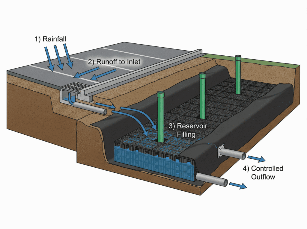
An underground stormwater detention system is a below-grade facility designed to capture stormwater during a storm event, and release the stormwater at a controlled rate to minimize flood risk downstream. They are preferred when land availability is an issue, or the local land use zoning regulations prohibit surface water storage features. A supplier comparison can include underground stormwater solutions from Storm Manage, evaluated against the same design storm, allowable outflow, effective storage and maintenance-access requirements.
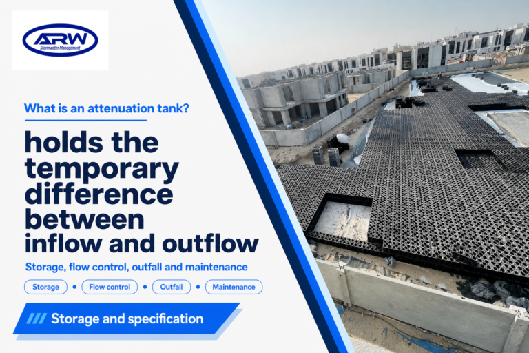
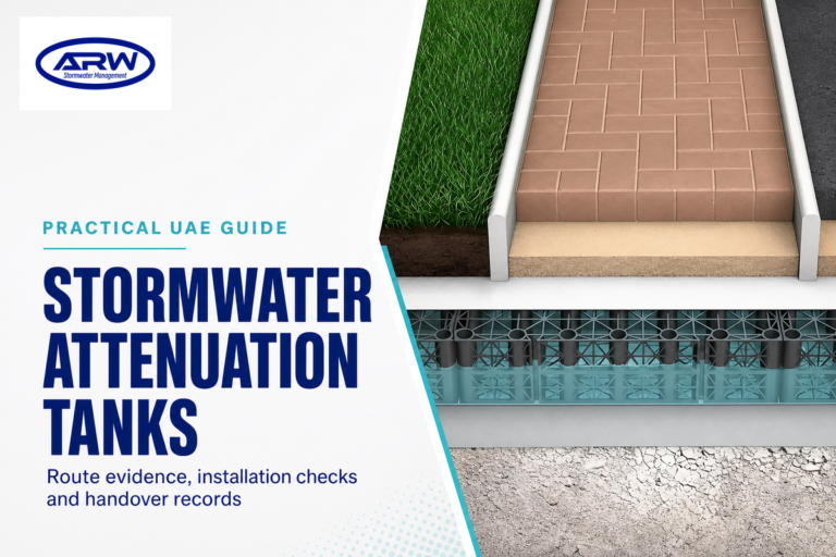
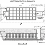
They work in a very specific way: when it rains, water flows into the system faster than it is released. The outlet is sized to discharge stormwater at a specific rate, equal to the pre-development runoff flow rate that the downstream drainage system was designed to accommodate. After the storm passes, the stored stormwater will drain back into the storm system after a period of a few hours. The system is then “dry” again. This is how detention differs from retention; with retention stormwater is stored in a pond permanently, often for infiltration or reuse. To see how detention systems relate to other similar systems, you may find our stormwater detention tanks page helpful to read, as it discusses systems made of individual detention structures (tanks), or our attenuation tanks page which gives the alternative terminology for these systems as used in UK and Australia.
Core Function: Temporary Storage and Controlled Release
The main purpose of an underground detention system is peak flow attenuation. When impervious surfaces such as roofs, roads, and parking lots replace natural ground cover in an existing landscape, stormwater runoff will have a much higher flow rate and volume during rainfall events. Detention systems catch this peak runoff, and restrict it to a controlled rate of release, commonly an orifice or weir plate, in a way that prevents downstream flow from exceeding the capacity that it was designed to accommodate. According to the CT Stormwater Quality Manual, “underground detention is a best management practice that is proven to be effective for the management of post-development peak flows”.
Detention vs Retention: Why It Matters
People often use these terms interchangeably, which is unfortunate because using the wrong term usually results in installing the wrong system. Detention is the practice of storing stormwater temporarily at a metered discharge rate, so that the pond or detention system is dry after the storm. Retention refers to the permanent storage of stormwater, generally for infiltration to the underlying geologic formation, or for use in a landscape irrigation system or other beneficial reuse, such as fire suppression water supplies or non-potable flushwater. Most stormwater management detention basins for new or redeveloped commercial sites, including underground detention systems, will be designed and built as detention facilities since, in most cases, local authorities mandate controlling the discharge rate, but not the elimination of the discharge itself.
Types of Underground Detention Systems
Quick Answer
Most projects come down to a choice between four system types: concrete vaults for heavy-traffic areas, corrugated metal pipe for linear sites, HDPE pipe for light-duty residential applications, and modular geocellular crates for large-footprint commercial sites needing maximum storage per cubic foot of excavation. ASCE has documented structural failures in plastic systems installed without proper load verification, making this a safety decision as much as a cost decision.
Most projects come down to a choice between four system types: concrete vaults for heavy-traffic areas, corrugated metal pipe for linear sites, HDPE pipe for light-duty residential applications, and modular geocellular crates for large-footprint commercial sites needing maximum storage per cubic foot of excavation. ASCE has documented structural failures in plastic systems installed without proper load verification, making this a safety decision as much as a cost decision.
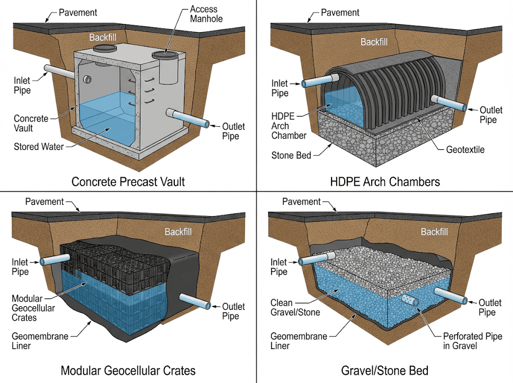
Selecting the optimal underground detention system requires careful consideration of material, load condition, storage requirements, and budget. Selecting a system is not simply a question of material cost but a complex engineering decision. Concrete vaults, for instance, may offer superior longevity but come with significant handling and installation costs, while lightweight plastic systems often demand precise backfill compaction to achieve their load ratings.
The CT Stormwater Quality Manual classifies the various materials used in underground detention and highlights several characteristics and considerations that each material type brings. One important thing to remember: ASCE published findings in 2024 documenting failure cases involving underground plastic detention systems under traffic loads, warning that improper load-rating assumptions have led to structural collapses in real-world installations.
Concrete Vaults and Box Culverts
Concrete vaults and box culverts are the most common materials used underground detention due to their strength and high bearing capacity (HS-20 and HS-25 loading). They typically do not require additional structural design and are therefore most commonly chosen for projects under streets, parking areas, and loading areas. According to the Concrete Pipe Association of the U.S. & Canada, precast concrete vaults can have design lives that exceed 75 years depending on the manufacturing and testing specifications (i.e. ASTM C1577 and C1433), but they can be difficult to maneuver during construction and tend to have the highest upfront costs per cubic foot of storage.
Corrugated Metal Pipe (CMP) Systems
Corrugated metal pipe systems generally consist of individual sections of galvanized or aluminized steel pipe with diameters ranging from 36 to 120 inches. The individual sections are manufactured as a single barrel, or connected with a corrugated metal manifold pipe to connect several single barrels together. Corrugated metal pipes are commonly employed for linear projects due to the ease with which these pipes can be connected in a straight line. They also have the benefit of being relatively economical for the storage volume that can be achieved. The main consideration for this technology is how long the galvanized material is likely to corrode under the existing groundwater conditions; depending on soil pH, the water table level, and other chemical constituents of the soils, galvanized pipe systems generally have a design life of between 25 and 50 years before becoming susceptible to failure. Polymer-coated CMP provides an alternate option for projects with groundwater conditions that would be particularly harsh on galvanized materials. These systems extend that range but add 15-25% to material cost.
HDPE Pipe Systems
HDPE systems are generally constructed of polyethylene pipe with diameters ranging between 12 and 60 inches. They are connected together using gasketed fittings to achieve a high watertight seal. These systems are generally lighter to install than CMP because of the smaller equipment and crew sizes that can be employed on these projects. HDPE has the inherent benefit of being completely immune to groundwater issues and typically has the longest design lives between 50 and 100 years due to the material’s non-corrosive nature. The key to using HDPE is that proper design and construction are critical for the long term success of these systems. If HDPE is selected for a detention application, then particular care must be taken with the structural design. This is particularly relevant because HDPE pipe systems were also the subject of recent warnings from ASCE regarding the importance of meeting the minimum backfill requirements and adhering to a design load based on traffic type.
Modular Geocellular Crate Systems
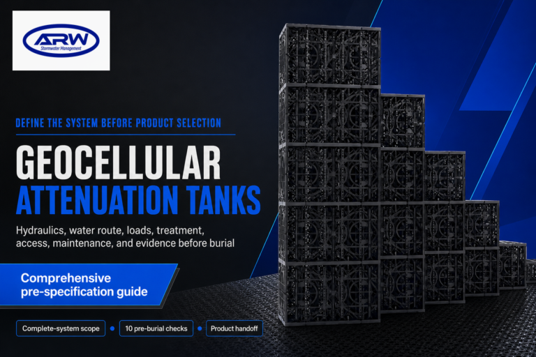
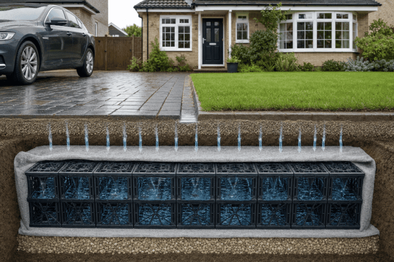
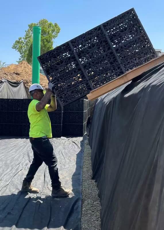
Geocellular systems consist of a modular, high strength, polymeric crate modules that are typically assembled on-site and wrapped with geotextile fabric. The high void ratio of these systems (in many cases exceeding 95%), makes them an ideal technology for projects that need to maximize the volume of available stormwater storage within a minimal excavation. Examples of these types of systems include Geocellular detention tanks (Aqua Rainwater) and modular stormwater modules (Aqua Rainwater). The modular design of these systems enables installation by equipment that can maneuver in tight spaces without requiring significant heavy lifting equipment to place. One limitation of this technology is that the load capacity is a function of the quality, grade and configuration of the individual crate material and thus load capacities can vary substantially across different manufacturer’s materials. Geocellular tanks and modules must therefore be specifically rated for a load condition to support a particular design condition. AQUA no longer supplies arch chambers. For current product options, see our underground stormwater solutions.
| System Type | Material | Load Rating | Typical Application | Key Limitation |
|---|---|---|---|---|
| Concrete Vault | Precast reinforced concrete | HS-20 to HS-25 | Roads, parking lots, heavy traffic areas | Heavy; requires crane installation |
| CMP Detention | Galvanized/aluminized steel | HS-20 with proper cover | Linear sites, highway medians, utility corridors | Corrosion in aggressive soils (pH < 5 or > 9) |
| HDPE Pipe | High-density polyethylene | HS-20 with engineered backfill | Residential, light commercial, low-traffic areas | Requires strict backfill compaction to meet load rating |
| Geocellular Crate | Polypropylene modular units | Varies by manufacturer (25-80+ tonnes/m2) | Large commercial sites, shallow excavations | Load rating varies; verify testing data per manufacturer |
| Arch Chamber | HDPE or polypropylene | AASHTO H-20 (rated models) | Infiltration-compatible sites, open-bottom applications | Not suitable for watertight containment without liner |
How Underground Detention System Sizing Works
Quick Answer
Storage volume is driven by five measurable inputs: catchment area, impervious surface percentage, design storm return period, allowable discharge rate, and local rainfall intensity. Getting any one of these wrong means the system either fails during design storms or wastes budget on unnecessary capacity. The Rational Method (Q = CiA) remains the standard starting framework for most US jurisdictions.
Storage volume is driven by five measurable inputs: catchment area, impervious surface percentage, design storm return period, allowable discharge rate, and local rainfall intensity. Getting any one of these wrong means the system either fails during design storms or wastes budget on unnecessary capacity. The Rational Method (Q = CiA) remains the standard starting framework for most US jurisdictions.
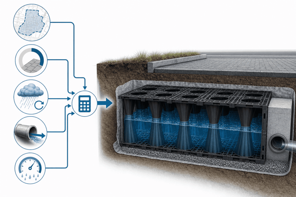
Determining the correct storage volume is the most critical engineering task in any underground detention system project. Get it too small, and the project fails code compliance and worsens downstream flooding during design storms. Get it too big, and you’ve blown the budget and dug more ground than necessary. Fortunately, the logic is straightforward: if you know the key design inputs, you can easily verify that a contractor’s proposal is actually appropriate for your site.
Across the United States, stormwater detention mandates almost always rest on a basic premise: the runoff rate after construction should be no higher than the rate before development for a particular design storm. Connecticut’s CT Stormwater Quality Manual offers step-by-step design instructions for calculating this storage volume, starting from catchment area mapping all the way through sizing. A comparable design approach exists in the Philadelphia Water Department Manual. It, too, specifies a design requirement for subsurface detention system sizing: the first inch of runoff from each impervious surface must be managed from the development site.
Key Sizing Parameters
Five specific parameters determine the necessary volume for underground detention sizing. Reliable values for these parameters are needed before any calculations can begin.
| Parameter | What It Means | Where to Find It |
|---|---|---|
| Catchment Area | Total land area draining to the detention system, measured in acres or hectares | Site survey or GIS delineation of drainage boundaries |
| Impervious Surface Percentage | Fraction of the catchment covered by non-permeable surfaces (roofs, pavement, concrete) | Site plan calculations; typically 60-95% for commercial developments |
| Design Storm Return Period | The storm frequency the system must handle (e.g., 2-year, 10-year, 25-year, 100-year event) | Local stormwater ordinance or MS4 permit requirements |
| Allowable Discharge Rate | Maximum outflow rate permitted, usually matching pre-development peak flow | Local stormwater ordinance; often expressed in cubic feet per second (cfs) |
| Rainfall Intensity | Rate of rainfall for the design storm duration, specific to project location | NOAA Atlas 14 precipitation frequency estimates for your county |
In terms of how these parameters work together in a real, municipal stormwater design scenario, Hamilton County’s BMP Manual is an excellent example of what’s needed.
The Rational Method Framework
The Rational Method (Q = CiA) is the most common method for sizing small and medium catchments’ detention systems in the United States. The runoff flow rate (Q) is the result of the runoff coefficient (C), rainfall intensity (i), and catchment area (A). Although this method can be inaccurate for larger or more complicated catchments, most commercial or residential stormwater detention system design calculations use it as their default starting point.
The runoff coefficient defines what portion of the rainfall is runoff. An open grass catchment (with permeable soil) might have a coefficient of 0.2 to 0.4. In comparison, an impervious commercial site might range from 0.85 to 0.95. The change in coefficient between pre-development and post-development scenarios is what ultimately dictates the storage required. Our article on how attenuation tanks work provides more information about the principles of flow rate attenuation.
Storage Volume Calculation
Required storage is calculated by finding the volume between the inflow of the post-development hydrograph and the acceptable outflow flow rate for the duration of a design storm. Typically, engineers will use one of the following calculation methods:
The simplified method is to take the difference between the post-development peak and the maximum design outflow, multiplied by the storm duration. This gives a very rough estimate for small projects and often results in an insufficient design storm duration or catchment area that might have multiple peaks.
The routing method calculates a time-step simulation of inflow and outflow over the duration of a storm. This is a more exact process and is necessary for most municipalities for final design submission. CSPI’s Design Manual has a number of worked examples of both methods applied to pipe-based detention systems.
📐
Engineering Note: Most US municipalities require detention systems to manage the difference between pre-development and post-development peak flow for a specified design storm. The design storm return period varies by jurisdiction, ranging from 2-year events for routine drainage to 100-year events for flood control, so always verify your local ordinance requirements before finalizing underground detention sizing.
When You Need Underground Detention: Regulatory Drivers
Quick Answer
No single federal law mandates underground detention for every US project, but the layered structure of NPDES permits, state stormwater programs, and local ordinances means most commercial developments adding significant impervious surface will trigger a detention requirement. The trigger almost always originates at the local level through impervious surface thresholds.
No single federal law mandates underground detention for every US project, but the layered structure of NPDES permits, state stormwater programs, and local ordinances means most commercial developments adding significant impervious surface will trigger a detention requirement. The trigger almost always originates at the local level through impervious surface thresholds.
It may surprise you to learn that, currently, no federal law in the US mandates that all projects install underground stormwater detention systems. There is a system in place, however, that starts at the federal level and continues at the state and local level which can trigger stormwater requirements and detention, if a project has certain characteristics. The first step in determining whether you need underground detention is understanding what requirements may exist in a locality and how they relate to your project.
The federal Clean Water Act (CWA) has created the National Pollutant Discharge Elimination System (NPDES) which essentially creates the US stormwater regulatory system. NPDES permits are a part of individual state’s implementation of the CWA and generally dictate that a municipality with a Municipal Separate Storm Sewer System (MS4) permit must manage post construction stormwater in their MS4 discharge to help control non-point source runoff from new construction and redevelopment. That is the mechanism which drives local stormwater ordinance requirements which can include underground stormwater detention.
Federal and State Stormwater Requirements
At the federal level, the Phase I and II CWA stormwater rules require MS4 operators to control post construction stormwater from any one or more acre disturbance projects. State requirements generally include all of the requirements for NPDES permit issuance and MS4 permits plus any standards at the state level. State standards may include structural best management practices like underground stormwater detention systems (or other requirements) that must be installed when a development has an impervious surface above certain state regulatory limits. An example of this is the CT Stormwater Quality Manual (Stormwater Best Management Practices) which has stormwater underground detention as one of the stormwater BMPs and lists specific design standards. Similarly, in Florida, the St. Johns River Water Management District has guidance for communities and HOAs for what their stormwater system requirements could be that includes underground detention.
Local Ordinance Trigger Points
At most, there is a specific ordinance at the local level that establishes stormwater requirements including underground stormwater detention and/or other requirements. There are several ways a municipality’s stormwater ordinance can dictate whether a property owner needs to install underground stormwater detention. Generally, these are threshold amounts of impervious surface area or site disturbance area that require an on-site detention. An example of this is the Philadelphia Water Department Stormwater Requirements which includes stormwater subsurface detention requirements for a commercial development that adds over a certain amount of impervious surface plus other design standards which include underground stormwater detention and stormwater BMP design.
Another way an ordinance dictates underground stormwater detention is the amount of impervious surface area that a proposed development will cover. Generally, a commercial development with over 5,000 to 10,000 square feet of impervious coverage, a redevelopment where the amount of existing impervious coverage will increase over a certain percentage or a new development where the amount of proposed impervious coverage increases over a certain area. Underground stormwater detention specifically could be used where a surface pond is not an option for the project, or there is not enough space on the property to construct a surface stormwater basin, or stormwater runoff would be allowed through a storm sewer system due to the setback requirements of a new parking structure or storm sewer improvements, etc.
💡
Pro Tip: Check your local stormwater ordinance before starting project design. Trigger thresholds for underground stormwater management detention requirements vary significantly between jurisdictions, and early identification of the requirement prevents costly redesigns later in the permitting process.
Installation Process and Best Practices
Quick Answer
The difference between a detention system that performs for decades and one that fails within years almost always traces back to three installation factors: backfill compaction quality, minimum cover depth compliance, and buoyancy management in high-groundwater areas. Every step from excavation through final backfill directly affects structural integrity.
The difference between a detention system that performs for decades and one that fails within years almost always traces back to three installation factors: backfill compaction quality, minimum cover depth compliance, and buoyancy management in high-groundwater areas. Every step from excavation through final backfill directly affects structural integrity.
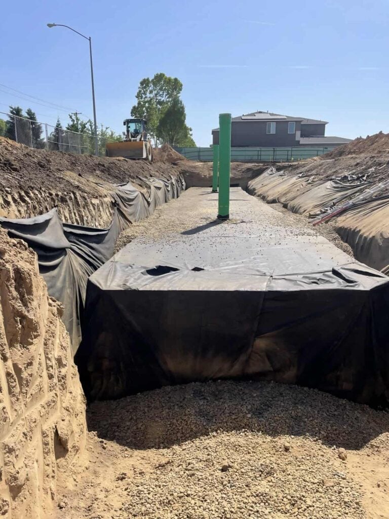
A sound underground detention design can be totally undone by installation that does not follow the engineered design. A sequence of events from the initial excavation to the final backfill compaction can have a significant effect on the integrity of an underground detention installation and on the long-term hydraulic performance of the system. For example, the difference between a system that performs for decades and one that develops problems within the first few years almost always traces back to installation quality control.
The installation requirements and best practices for underground detention are well documented in various BMP Manuals, such as Hamilton County BMP Manual. In this case, requirements for minimum cover, compaction specifications and setbacks for underground detention systems apply specifically to Hamilton County. Similar BMP manuals for other jurisdictions are referenced in the resources section, although your specific jurisdiction may have slightly different requirements.
Site Preparation and Excavation
Proper site preparation starts before excavation begins and includes verifying that the location and size of the planned excavation conforms to the approved engineering design and that all utility locates have been completed. Proper installation of underground stormwater detention systems is a very critical issue that requires that excavation grades and locations conform with the approved design plans so that the detention system inlet and outlet invert grades are as designed in order to ensure proper hydraulic performance of the entire stormwater drainage system.
In addition, a minimum of 12 inches wider than the footprint of the system must be excavated on all sides to allow the system contractor room to connect pipe, compacting and placing backfill material. The excavation subgrade should be compacted to a minimum specified density, typically 95% Standard Proctor, and must be checked with a nuclear density gauge or other suitable testing procedure, before any bedding material is placed. If dewatering is required to install the underground detention system, dewatering should continue throughout the installation and backfilling process; it is not acceptable to install a buried stormwater detention system, compact and backfill it and have a standing pool of water in the excavation when installation is complete. Compaction of backfill material will be compromised if performed in wet soil or water, and there is significant possibility of developing voids in the soil around the system which can lead to settlement and premature failure of the system.
System Placement and Backfill
The bedding material, which consists of a clean crushed stone or compacted granular fill material provides a good base for the buried stormwater detention installation to rest on. The thickness of the bedding material required will vary by system. For example concrete vault systems require a minimum of 6 inches of compacted granular base and pipe systems may vary between 4 and 12 inches, depending on system pipe diameter and soil conditions.
After placing the system in the excavation, the system needs to be carefully backfilled in lifts of 6 to 12 inches and compacted to specifications, allowing the soil to settle before any additional fill material is placed. Failure to carefully backfill and compact the system as specified is the primary reason underground detention systems settle after installation. Placing the system in the excavation and then dumping backfill in a lump and compacting it to the specified density does not allow the soil to settle in a controlled manner and may shift and move the system during this installation process and result in joint failure at pipe connections. This is clearly illustrated in Philadelphia Water Department specifications for plan review standards for subsurface detention. For subsurface stormwater management systems using modular designs, following manufacturer-specific backfill guidelines is critical since each product has different load transfer mechanisms.
Once the stormwater detention system is in place, the inlet and outlet pipes must be connected to the system in a manner that allows for any minor settlement without creating gaps and causing the pipes to leak. Access inspection ports and manholes should extend to finished grade to allow for ready access for maintenance personnel in the future.
Common Installation Mistakes to Avoid
Three of the common installation failures or deficiencies that are observed in the performance of underground detention systems are inadequate backfill compaction and insufficient cover depth. Each of these can occur during installation of a system and be corrected before completion of installation. It is a mistake to assume that any buried detention system will perform well and function for many years if proper installation techniques are not followed.
The most common installation deficiency for underground detention is inadequate compaction of fill material placed around the system after it is placed in the excavation. If the bedding and backfill material is not compacted in lifts as required by design, the surrounding soil will settle unevenly in the future, placing uneven loads around and on the detention structure, which may eventually cause damage or failure of the buried stormwater detention system. In the case of pipe based systems, the uneven loadings may result in the deflection of a buried pipe being outside allowable deflection limits. For modular geocellular type systems, uneven loadings may result in deformation or partial failure of crate modules. Refer to our geocellular attenuation tank guide for additional best practices for installing geocellular stormwater systems.
A second most common cause of failure of a buried stormwater detention system is that insufficient depth of cover was provided to allow the system to be properly installed and function well for many years. The design of every buried stormwater system includes a minimum cover required over the top of the system in order to provide the design vehicle loading capacity for the structure being installed. Failure to install a buried detention system with the minimum required cover depth will result in a system with less cover depth, which may lead to premature system failure due to loading exceeding design capacity. The system may not fail, particularly in light traffic areas, and it may perform for years before problems begin to occur. However, it is important to install a stormwater detention system with minimum required cover depth as specified in order to ensure system will perform as expected for many years with minimal maintenance.
⚠️
Warning: Always verify buoyancy calculations in high groundwater areas. Flotation of empty underground detention systems during rising water tables is a documented failure mode that can lift entire structures out of alignment. When the groundwater table is above the system invert, anti-flotation measures such as concrete anchor pads, hold-down straps, or ballast backfill must be engineered into the design.
Muller Engineering describes the effect of poor installation quality of stormwater systems on the long term performance of detention systems and the additional maintenance and costs that may result from poor installation.
Cost Factors and Long-Term Value
Quick Answer
Underground detention typically costs more per cubic foot than a surface pond, but the economic comparison reverses when you account for the buildable land recovered by going below grade. In commercial markets where land trades above $20 per square foot, the land value recovery alone can exceed the underground system's entire construction premium.
Underground detention typically costs more per cubic foot than a surface pond, but the economic comparison reverses when you account for the buildable land recovered by going below grade. In commercial markets where land trades above $20 per square foot, the land value recovery alone can exceed the underground system's entire construction premium.
Often, cost discussions regarding underground detention fall flat when the material costs are considered in isolation without considering the land value recovered by being underground. A surface detention pond in a 10-acre commercial development site may use as much as 15,000 to 25,000 square feet of developable area. In commercial developments where the market price of land ranges from $15 to $50 per square foot, a detention pond could cost from $225,000 to $1.25 million in lost revenues due to the undeveloped land, not taking into account the construction costs of the surface pond itself.
This is the reason, often not considered in any cost comparisons, that underground detention can often cost less than surface detention due to the lost potential of the surface detention pond. In NAIOP’s analysis, the underground detention is seen as an effective way to recover the surface area that would otherwise be used by a surface detention pond.
Primary Cost Drivers
There are five key drivers of the cost of an underground stormwater detention tank that will lead to wide price variations in the cost per gallon or cubic foot that any given company or individual may quote:
Material Selection The material selected will be the single largest variable in the unit cost of the detention tank. The precast concrete vault is more expensive per cubic foot than other materials in its unit cost, but may require less engineering and material costs associated with backfilling and other considerations. The HDPE pipe and geocellular crate system is less expensive per cubic foot, but may require more engineering and material costs associated with backfilling and other considerations. The CT Stormwater Quality Manual states that the material selected will affect both the initial cost and maintenance considerations.
Storage Requirement The amount of storage required will drive the second highest factor in the material and installation cost. Due to the fact that more complex inlet and outlet piping configurations and larger inspection chambers will be necessary to accommodate the increased number of pipes and flow, the increased storage capacity may also lead to increased construction cost.
Site Conditions The specific location of the site, specifically the soil conditions, depth to the water table, and utility lines can impact the final cost of a detention vault more significantly than the choice of storage material. Excavation in rock, high water tables which will require dewatering, and utility relocations can each increase cost by an estimated 20-40%.
Depth of Burial The greater the depth of a given underground detention vault will increase cost. This is due to the fact that the more soil that will need to be excavated to install the tank and the amount of support that will be required to do so. If a shallow layer of bedrock exists near the surface, that may also limit the depth that can be used for the installation.
Access Requirements Due to the requirement to maintain the system, the underground vault will have to be accessed. This means that more access manholes or inspection ports will increase overall cost of the construction of the detention vault. The local municipality or agency will have requirements regarding access. Any compromise on access required during the construction can lead to an expensive retrofitted situation.
Underground vs Surface Pond Economics
| Cost Factor | Underground System | Surface Pond |
|---|---|---|
| Land consumption | Zero surface footprint; buildable land above | Dedicated surface area required; land cannot be developed |
| Construction cost | Higher per cubic foot (excavation, materials, backfill) | Lower per cubic foot (earthwork, grading, outlet structure) |
| Maintenance access | Requires manholes and confined-space entry protocols | Open access; visual inspection from grade |
| Long-term maintenance cost | Moderate; sediment removal via vacuum truck | Lower routine cost; periodic sediment dredging and mowing |
| Aesthetics and liability | Invisible; no open water safety concerns | Visible; may require fencing and signage for liability |
| Land value recovery | Full development potential above system | None; land dedicated permanently to stormwater function |
For the cost of a surface pond vs. an underground pond, we have to look at the cost to own for each option, rather than simply the upfront price tag. It often makes economic sense to opt for the underground system in urban and suburban commercial development areas where the land value is valued over $20 per square foot. For rural or less developed sites where land is plentiful and not as expensive of an investment, a surface pond will still be an economical choice. GreenRise has project-level costs that support that the decision to construct an underground detention structure vs. a surface pond will be based on the site conditions and economics rather than the construction cost alone.
💡
Pro Tip: Underground detention can recover thousands of square feet of buildable land compared to surface ponds. When comparing options, factor your local land value per square foot into the cost analysis to get an accurate total project economic picture.
Ready to evaluate costs for your specific project? Get a free quote from our engineering team.
Ready to evaluate costs for your specific project?
Maintenance and Inspection Requirements
Quick Answer
Annual inspection and sediment removal when accumulation reduces effective storage volume are the baseline requirements for all underground detention systems. Systems with documented maintenance protocols perform reliably for 50+ years; systems without them degrade within the first decade as sediment reduces storage capacity below permitted thresholds.
Annual inspection and sediment removal when accumulation reduces effective storage volume are the baseline requirements for all underground detention systems. Systems with documented maintenance protocols perform reliably for 50+ years; systems without them degrade within the first decade as sediment reduces storage capacity below permitted thresholds.
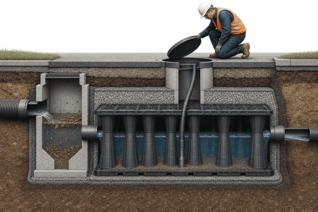
Underground detention systems must be maintained on a scheduled basis if they are to continue performing effectively over the 50+ year design life. Lack of inspection and sediment removal is the most prevalent cause for these systems to lose storage, and ultimately not function to the discharge rate permitted. In more than 15 years of designing and maintaining stormwater detention systems for both commercial and municipal facilities, it is clear that those systems with a regular maintenance protocol are the most likely to perform as required, and those that do not, typically show deterioration in the first 10 years of operation.
The CT Stormwater Quality Manual states: Underground structures should be inspected annually. If sediment buildup has accumulated to a level that decreases the total storage volume available within the structure, remove the excess sediment. This is not optional guidance. Many MS4 permits do require proof that maintenance has occurred.
Routine Inspection Schedule
An underground stormwater management system should be inspected annually. A visual inspection is the easiest and most economical way to monitor the health of a stormwater control measure. The best time to inspect a facility is after the wet season has concluded and before the following wet season begins. At this point, any sediment that has accumulated during the previous wet season is easily visible and the system is easily accessible to maintenance personnel.
For every inspection, the following items must be recorded:
- Condition of inlet and outlet structures
- Any blockage of orifice plates and/or weir openings
- Depth of sediment at multiple points within the system
- Condition and accessibility of manholes, inspection ports, and any other access features
Muller Engineering utilizes the following checklist for all routine inspection reports :
- Structural condition
- Sediment depths
- Inlet/outlet functionality and blockages
- Vegetation at inspection and access points
All underground stormwater control measures that include pipes should have CCTV inspections every 3 to 5 years for documentation of condition. This is necessary because the internal condition of the system cannot be effectively evaluated through visual inspection from manholes.
Additionally, post-storm event inspection should occur following storms greater than the 10-year design storm. Inspection within 72 hours of such an event allows for removal of debris, assessment of damage to outlet controls, and sediment management. The latter is important as these events can mobilize debris, damage outlet controls, or deposit sediment volumes that significantly reduce available storage prior to any future wet season.
📐
Engineering Note: Annual inspection of underground detention structures is recommended per state BMP guidelines, with sediment removal triggered when accumulation reaches a depth that measurably reduces effective storage volume. Documenting each inspection is a compliance requirement under most MS4 permits.
Sediment Management and Cleaning
The single most frequent maintenance issue for an underground detention system is sediment accumulation. Every storm event results in some amount of sediment loading into the facility in the form of fine particulate and organic matter, which in some cases includes trash. As this material settles within the detention system, it becomes consolidated and reduces the amount of available storage.
Methods of sediment removal are generally dependent on system type and type of access to the system. For pipe-based systems, vacuum trucks are the most common method of sediment removal. The vacuum truck will have a long, flexible vacuum hose, which can be fed through a manhole into the interior of the system. The accumulated sediment is then removed in a fluid state. Confined-space entry by certified personnel may be the only method of sediment removal for large concrete vaults or facilities without direct access for a vacuum truck.
Geocellular storage presents different maintenance challenges. The crate structure of geocellular systems often makes vacuum cleaning less efficient because sediment can settle in cell space that is not directly accessible from the surface. In order to minimize sediment loading, a modular system should always have some form of pretreatment upstream of the detention system, such as a sediment forebay or hydrodynamic separator to capture the majority of suspended solids prior to the system inlet.
The Lake Superior Streams toolkit offers guidance on how to develop a maintenance schedule and handle maintenance events for underground storage. According to Aqualisco, a maintenance contract with a stormwater contractor will ensure regular maintenance inspections are occurring and minimize the chance of sediment accumulation compromising the facility performance.
Frequently Asked Questions About Underground Stormwater Detention
While this guide covers the general design and construction of underground detention systems, it is impossible to discuss this topic without addressing the practical questions often raised by engineers, developers, and property owners as they evaluate such systems for their specific projects. Here are answers to some of the more common questions we get about underground detention.
We have referenced these topics in a similar manner throughout the rest of the guide, with source references cited for the CT Stormwater Quality Manual, the Philadelphia Water Department, and the American Society of Civil Engineers’ (ASCE) analysis of system performance. We have also included information on the range of requirements among different jurisdictions and the recommendation to verify the requirements for your specific project in the proper local standard.
References
[1] Warning: Underground plastic stormwater detention systems
[2] Underground Detention – CT Stormwater Quality Manual
[3] 4.8 Subsurface Detention – Development Services
Related Articles
About the author

Grayden Du
Export Director · AQUA RainWater Solutions
Grayden Du is Export Director at AQUA RainWater Solutions. His work spans geocellular detention systems, underground stormwater storage and subsurface water management. Drawing on more than 16 years of hands-on experience across over 30 country markets, he explains technical principles, system choices and practical project requirements.
About AQUA RainWater Solutions
AQUA RainWater Solutions manufactures geocellular stormwater modules, shallow attenuation systems and ground-reinforcement grids, and coordinates the supply of geomembranes, geotextiles and EPDM pond liners. We help match system interfaces and specifications, with batch inspection for moulded products, product documentation and export-delivery support.