Get in touch with AQUA Company

Updated September 2026
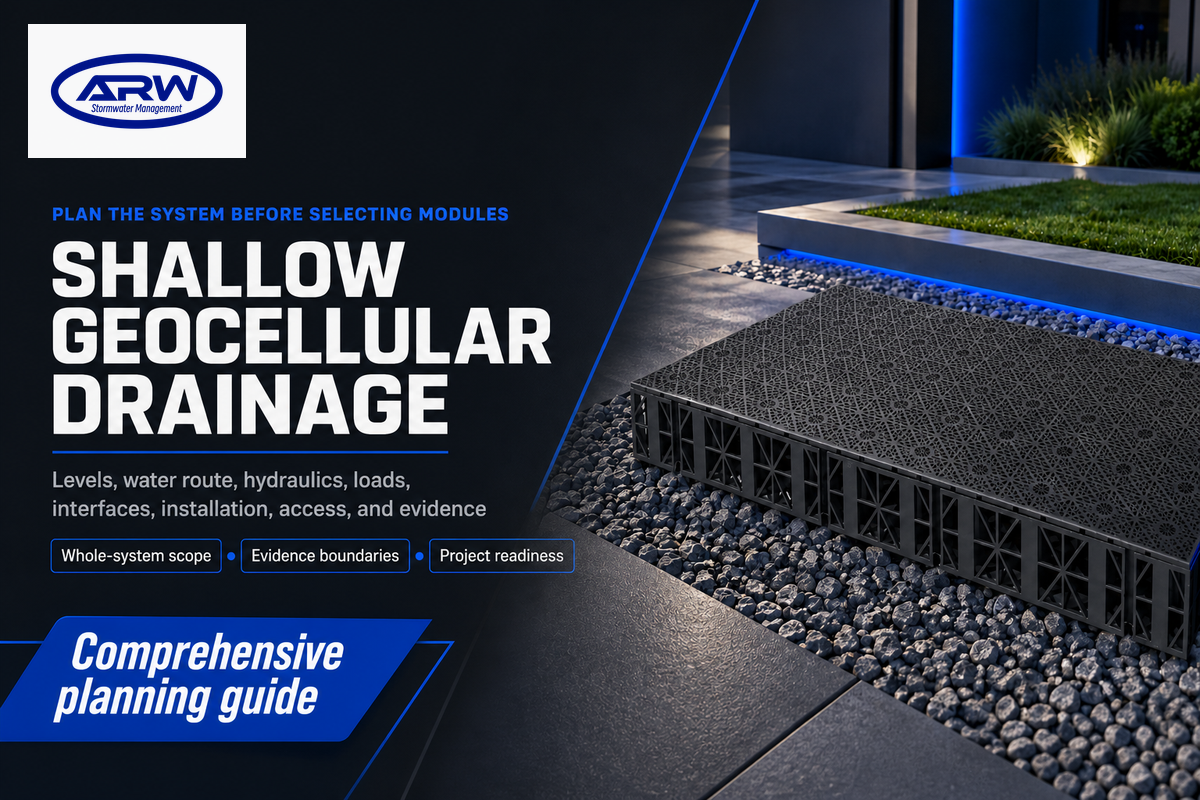
A Shallow Geocellular Drainage System is a low-profile underground arrangement used where vertical build-up is constrained, but module height isn’t the only concern. The complete system must address runoff, store or infiltrate it, carry the project load cases, connect to site drainage, protect water quality, allow inspection, and provide a safe path when the design event is exceeded.
Therefore, the first approach should be to establish a defined project scope and not to count crates. Whether a shallow layout is workable depends on surveyed levels and groundwater, the runoff source, field infiltration evidence, discharge conditions, loading, wrapping, pretreatment, access, construction hold points, and assigned maintenance responsibility. For stormwater management, product data sheets alone can’t define how surface water runoff moves through a site.
This planning guide establishes the evidence boundary and the planning sequence; it does not assign project-specific depth, storage capacity, load rating, design life, maintenance regime, construction controls, or approval. Site conditions, jurisdiction, named products, the governing calculation method, competent-design input, construction controls, and the approving authority determine those values.
In practice, a shallow geocellular drainage system is a low-profile underground storage zone plus the hydraulic, structural, filtration, connection, access, construction, and maintenance interfaces that make the zone function. The module is a component; the project team still has to prove that the complete installed system fits the site.
Scope boundary
Use this article to review and challenge project inputs. Use the existing solution page for project-specific product configuration, fit review, and quotation. AQUA Rain Water supplies products, supporting materials, documents, and agreed technical support; it doesn’t present itself as the contractor responsible for the full installation.
What a Shallow Geocellular System Is, and Is Not
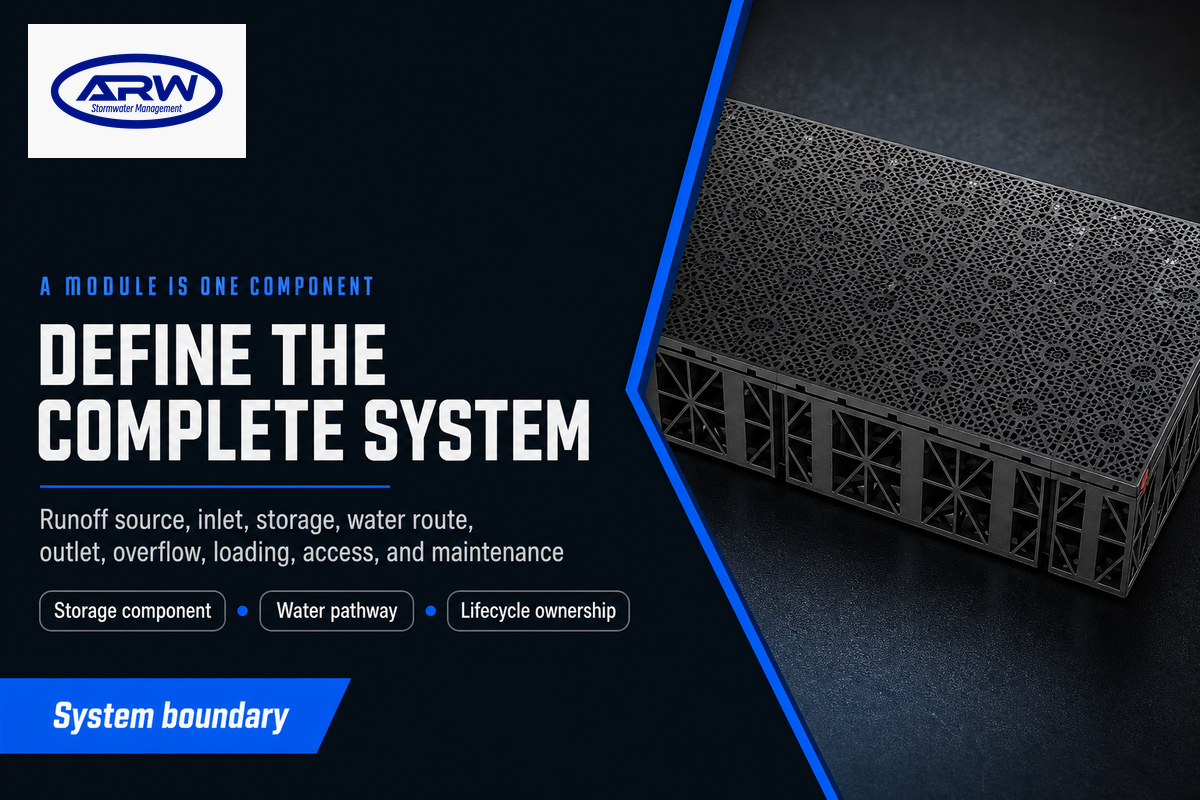
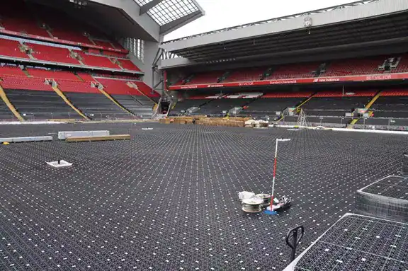
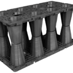
A shallow geocellular system is an underground stormwater arrangement built where vertical space is constrained. Molded modules create storage zones, while the rest of the system includes pipes, flow controls, covers, permeable or impermeable wrapping, pretreatment, access points, surrounding soil, and construction above. One stack of modules isn’t a complete system.
“Shallow” describes the selected build-up or geometry, and doesn’t add a specific depth. Geocellular attenuation tanks retain runoff for a defined release, while infiltration systems transfer runoff to the sub-soil. Controlled hybrid infiltration/attenuation systems may allow some infiltration, with excess water controlled and discharged at a permitted downstream location.
In a Sustainable Drainage System (SuDS), buried water storage is a component of surface water management. Green roofs, swales, basins, permeable surfaces, or treatment features may manage runoff earlier in the train; the buried zone should not displace a more suitable visible component merely because a compact module is available. Products described informally as soakaway crates are intended to infiltrate stored runoff into suitable ground.
Define the system boundary by naming its runoff source, inlet and storage zone; the intended water route; the outlet or receiving ground; the overflow or exceedance path; the overlying use and structural design basis; the inspection route; and the maintenance owner. Independent Susdrain guidance on geocellular storage systems likewise treats storage, treatment, structural suitability, monitoring, and maintenance as connected questions rather than a crate-only selection.
| Boundary item | Question it must answer | Not proved by module geometry |
|---|---|---|
| Hydraulic route | Where water enters, is stored, then infiltrates or discharges | Rainfall basis, flow controls, receiving point, overflow |
| Structural zone | How loads pass through cover, fill, modules, and formation | Long-term project performance under actual boundary conditions |
| Water-quality controls | How sediment and pollutants are kept out or managed | Treatment credit or groundwater acceptability |
| Lifecycle access | How assets are inspected, cleaned, and recorded | A practical maintenance route or responsible owner |
Start With Levels and Constraints, Not Module Height
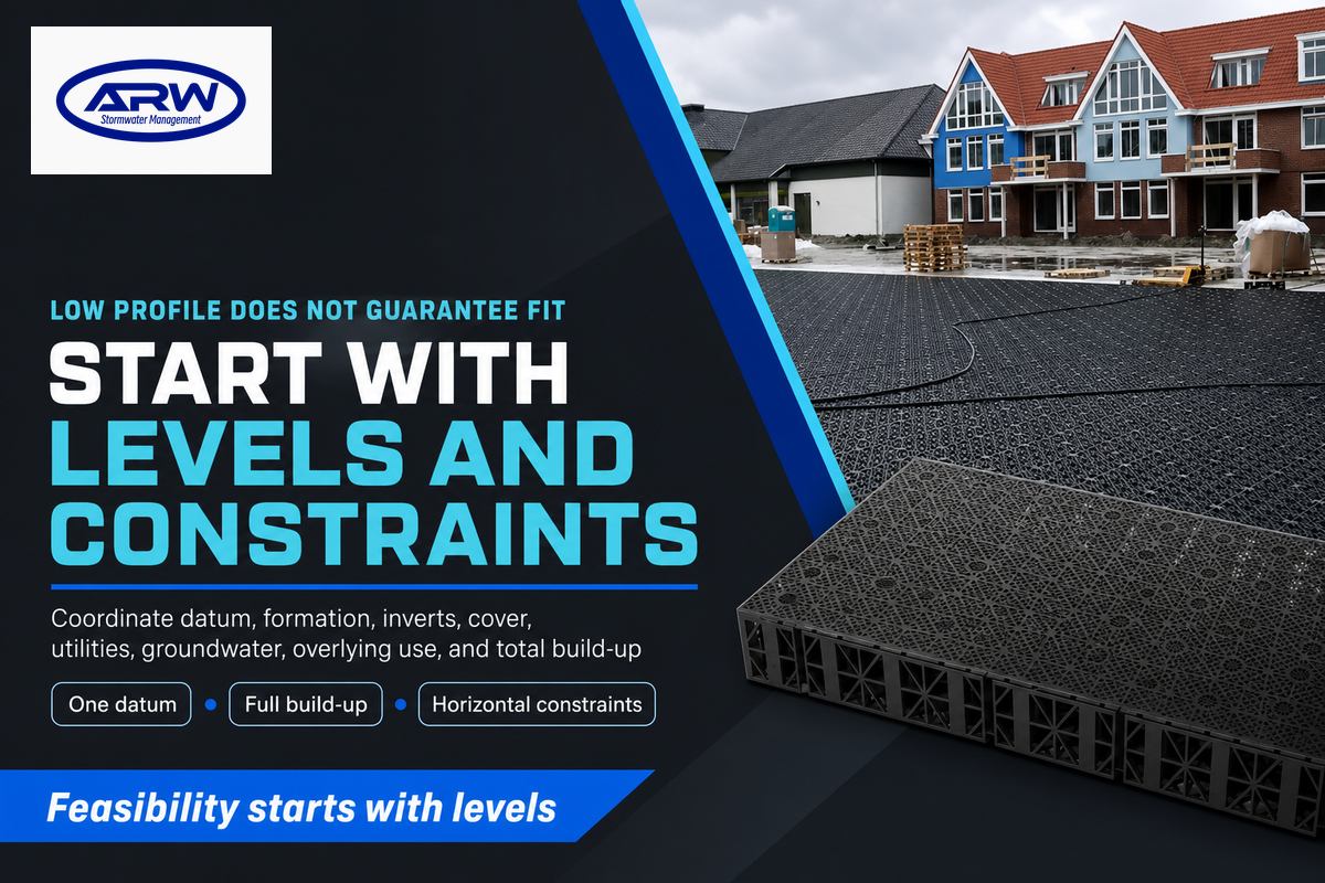
Feasibility starts with one coordinated level sheet. Indicate survey datum, formation, inlet and outlet inverts, available cover, utilities, groundwater observations, overlying use, and total construction build-up. A low-profile module does not guarantee a fit: any added pipe gradient, outlet-level constraint, clearance, liner, bedding, or pavement layer can consume the available depth.
Align all collection levels to a common datum and show the drawing revision. One “available depth” measurement is ambiguous when different parties measure to formation, the top of a sub-base, or a finished surface. The layout must include horizontal constraints, including foundations, retaining structures, trees, services, easements, access zones, and any locally required separation.
| Input | Why it matters | Who confirms it |
|---|---|---|
| Datum and surfaces | Makes all elevations comparable | Survey and design team |
| Inlet and outlet inverts | Tests gravity route and available hydraulic head | Drainage designer |
| Formation and cover build-up | Defines the true vertical envelope | Civil and structural designers |
| Utilities and structures | Prevents geometric and access conflicts | Utility coordinator and design team |
| Groundwater observations | Affects infiltration, uplift, construction, and lining | Geotechnical or groundwater specialist |
| Overlying use and loads | Sets the structural load cases and construction restrictions | Project structural designer |
| Local clearances and approvals | May control location even when geometry fits | Approving authority and project designer |
| Inspection and maintenance access | Tests whether hidden controls can be reached, cleaned, and recorded | Asset owner and drainage designer |
How deep should a soakaway drain be?
No single depth can be assumed to be safe to copy from site to site. The build-up required will depend on the inlet levels, storage geometry, cover and loading, and formation and groundwater levels, as well as the soil and local conditions, and the nearby structures and rules. The depth-to-storage selector can be used to perform a preliminary assessment. However, the output still requires individual project engineering review.
Natural Resources Wales advises that sustainable drainage components should be shallow where possible, while also expressing a policy preference against buried geocellular soakaways in its context. In contrast, Cardiff Council states local conditions under which geocellular crate soakaways may be accepted. The exceedance route must be compatible with the site risk assessment; “the tank is large” is not a substitute.
Choose Attenuation, Infiltration, or a Controlled Hybrid
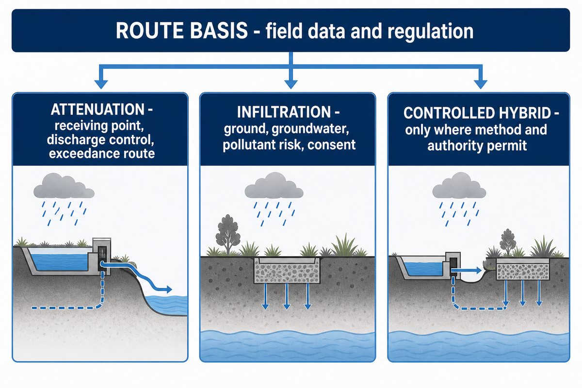
Selection between attenuation or infiltration is based on field data and regulation, not purchaser preference. Infiltration would require adequate ground, acceptable groundwater and pollutant risk, safe relationships to structures, and local consent. Any attenuation tank design requires a defined receiving point, allowable discharge rate, a flow control device, and an exceedance route. Controlled hybrids may be adopted where the design method and authority permit both functions.
For an infiltration concept, provide the test method, locations, depths, results, groundwater conditions, runoff source, history of contamination, setbacks, and the person who interprets them. England’s Current Approved Document H publication cites adequate infiltration where practicable and links the controlling guidance; it doesn’t make one test result applicable to all sites.
Water quality can affect the location of a facility even if soil permeability is favorable. The United States Environmental Protection Agency groundwater guidance asks designers to consider pollutant sources, prior land use, wells, pretreatment, and non-infiltration alternatives. Similarly, infiltration systems in the Oregon transportation guidance suggest that some infiltration facilities may be included in a specific underground injection control process. These examples demonstrate jurisdictional concerns and shouldn’t be considered generalized.
| Route | Core evidence | Required destination | Important limitation |
|---|---|---|---|
| Infiltration | Field testing, groundwater, pollutants, structures, local acceptance | Suitable receiving ground | Unsuitable ground or water-quality risk can rule it out |
| Attenuation | Allowable discharge, flow control, receiving point, event basis | Approved watercourse or sewer, or another accepted receiving system | Storage without an accepted outlet is not a complete concept |
| Controlled hybrid | Both evidence sets plus a defined excess-water control | Ground and a controlled receiving route | Local method and approval must explicitly permit the arrangement |
What is the difference between a soakaway and an attenuation tank?
The purpose of a soakaway is to infiltrate stormwater runoff into the surrounding soil. An attenuation tank stores stormwater runoff for release at a controlled rate to an accepted receiving point. Limited infiltration systems with a controlled excess route can be considered, but the assumption shouldn’t be made merely because both functions appear desirable.
When a buried geocellular route is a poor fit
A buried geocellular route deserves challenge when field evidence doesn’t support infiltration, runoff may threaten groundwater, an accepted discharge point is unavailable, safe exceedance routing can’t be provided, structural boundaries remain unresolved, or the project can’t create practical inspection and sediment controls. Surface-first sustainable drainage systems may deliver more visible treatment and easier maintenance where land and levels allow it.
Don’t purchase the geocellular modules without evidence of design completion. Design discussion should record the function, controlling authority, loading conditions, groundwater design basis, interfaces, and construction and maintenance owners. For an infiltration concept, record the test method, locations, depths, results, groundwater conditions, runoff source, contamination history, setbacks, and the person who interprets them. The shallow attenuation tank product page should be used only after attenuation is an accepted system, and it shouldn’t be used as evidence that attenuation suits all sites.
Define the Hydraulic Inputs Before Discussing Volume
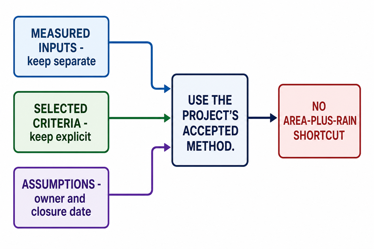
Storage volume is an output of a defined hydraulic method and not a result of an approximation based on roof area. To support the conversion of volume to modules, the calculation brief should state each contributing surface, rainfall basis, generation of runoff, initial conditions, criteria for event selection, basis of allowable discharge or infiltration, flow control, climate, and the local method under which the calculation is to be made.
Record field measurements separately from the criteria and assumptions selected for design. Examples of measured project inputs include surveyed areas and results from field infiltration work. Selected criteria may be design events or discharge allowed. Assumptions may be runoff response or initial state. Assign ownership to each assumption with a target date to close to avoid an undocumented preliminary design being accepted as complete.
Unconstrained excess water and its consequences should be described when the selected design event is exceeded or when an outlet becomes restricted. The excess water routes should be compatible with the site risk assessment and the construction hydraulic brief; “the tank is large” isn’t an answer. Additionally, where the design includes an impermeable wrap, the hydraulic brief should address groundwater uplift and anti-flotation during construction and operation. Pause the product discussion when the site team cannot name the hydraulic function, approval authority, load cases, groundwater basis, interfaces, construction verifier, and maintenance owner.
Calculation boundary
An area and a rainfall figure can’t safely determine a tank volume. Complete the governing inputs first, then use the project’s accepted method. The module quantity estimator is a bounded exploration tool after storage volume and a named configuration are available; it isn’t a drainage design engine.
Use Module Test Data as One Input to System Design
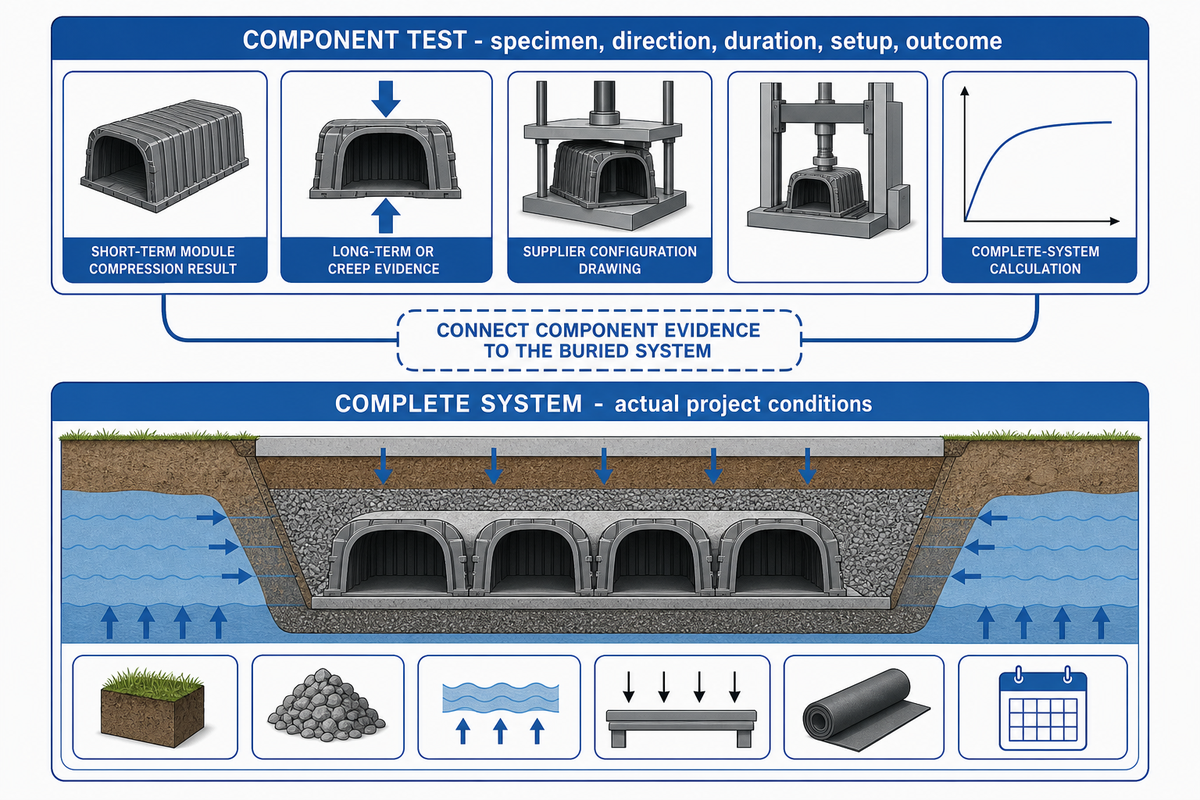
A module test result only supports conclusions within the tested specimen, loading direction, duration, setup, and reported outcome. The complete-system assessment remains the competent designer’s responsibility and must cover actual cover depth, soil and backfill, groundwater and buoyancy, traffic and construction loads, lateral effects, material factors, interfaces, and the design-life basis.
The current version of the PD CEN/TS 17152-4:2025 scope is instructive because it addresses structural design of complete underground modular systems while naming adjacent conditions outside its scope. This teaches designers that component evidence and complete-system variables must be connected explicitly; it doesn’t mean component evidence is unimportant.
The 2022 university journal study of geocellular samples also reported different behaviors based on loading direction, and reported the need for further design input for more complex applications. In this study, consider the example as a specimen-and-method case, not as a transferable design rating for another module or site.
“Module evidence answers a component question; project design must still connect that evidence to the complete buried system.”
AQUA Rain Water technical team
| Evidence object | Valid use | Still open |
|---|---|---|
| Short-term module compression result | Characterizes the tested specimen and setup | Long-term project behaviour and boundary conditions |
| Long-term or creep evidence | Supports a named material and design method | Project loads, soil, cover, groundwater, and interfaces |
| Supplier configuration drawing | Identifies the proposed module arrangement | Acceptance by the responsible project designer |
| Complete-system calculation | Connects declared inputs, method, factors, and load cases | Construction conformity and as-built evidence |
What model, direction, test method, duration, temperature, specimen condition, load definition, factors and exclusions does a result cover? When converting the gross geometric envelope into usable storage, apply a separately confirmed void ratio for the named product. Potential users who want to compare the different product lines can assess the geocellular tank product line and review available product families without confusing a product page with project approval.
Design the Interfaces Around the Geocellular Zone
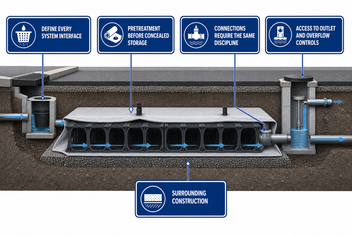
System interfaces control water pathways in and out and determine whether water remains manageable. The PD CEN/TS 17152-4:2025 complete-system scope reinforces why conditions beyond the module must be defined rather than left implicit. Draw and define the inlet, pretreatment, silt controls, pipe connections, wrap, outlet control, ventilation, inspection access, downstream connection, high flow bypass, and surrounding construction. One blank interface is not a minor drafting omission; it is a hidden project risk because the system decision has no owner.
Functionality dictates selection. In an infiltration design, permeable geotextiles allow separation of materials and let water flow. In a lined attenuation zone, a geomembrane can be used. Complete assembly details must coordinate compatible seams, penetrations, protection layers, transitions, and a specification written for the project. AQUA treats geotextiles and geomembranes as supporting procured products; neither should be considered part of the same injection-moulding line as the core modules.
Pretreatment must precede concealed storage. Sediment and debris, along with pollutant loads, differ across roof runoff, car-park runoff, landscaped areas, and construction-phase flows. Identify the control, its access, the cleaning method, the disposal route, and the control’s owner. If sediment can get to the storage zone, but there’s no removal path, maintenance has been deferred rather than designed.
Connections require the same level of discipline. Record elements including pipe diameter and level, opening method, sealing detail, support, flow direction, and the name of the individual accepting the modification. Outlet controls and overflow structures must have access for inspection. If ventilation is required, derive it from the named configuration and this project’s design; do not copy requirements from a different installation.
Plan Installation Handoffs Before Delivery

The control of installation begins prior to the arrival of modules. The project team should accept formation, bedding, sediment protection, assembly details, wrap and connections, permitted equipment routes, backfill method, inspection points, and record requirements. The project team should accept and record formation, bedding, sediment protection, wrap and connections, permitted equipment routes, backfill method, inspection points, each hidden interface, the responsible verifier, and every hold point. Each hidden layer needs a hold point while it’s still visually accessible, with the responsibility assigned to the appropriate project team.
Philadelphia’s subsurface infiltration practice manual provides a useful local example: it addresses construction oversight, sediment protection, heavy-equipment exclusion, and verification of dimensions, grades, elevations, and storage volume before backfill. The principle should be used by referring to the requirements for the actual project, rather than transporting the details of Philadelphia to other places.
- Release the formation — record levels, condition, bearing or geotechnical acceptance, groundwater observations, and any remediation.
- Confirm the setting-out — match the latest layout, inverts, clearances, storage footprint, and interface locations.
- Protect the work — control sediment, water, access, and heavy equipment before modules and wrapping are exposed.
- Inspect assembly and interfaces — verify the named configuration, connectors, wrap, penetrations, inlet, outlet, access, and protection details.
- Hold before backfill — capture dimensions, grades, elevations, photographs, nonconformities, and the responsible acceptance.
- Control backfill and compaction — follow the approved material, sequence, equipment, and test plan without applying direct loads outside the accepted route.
- Close the handover — issue as-built records, inspection results, operating information, maintenance ownership, and open-item status.
The supplier’s installation information pertains to the named product. Control and acceptance of the site-specific formation, loads, interfaces, compaction, and groundwater remain with the project engineer. AQUA may provide remote guidance, agreed site support, factory-witnessed tests, test video, or loading supervision; those services do not transfer contractor or designer responsibility to the product supplier. These installation records give the maintenance team evidence to inspect the accessible system before choosing a remedy.
Make Inspection and Maintenance Possible
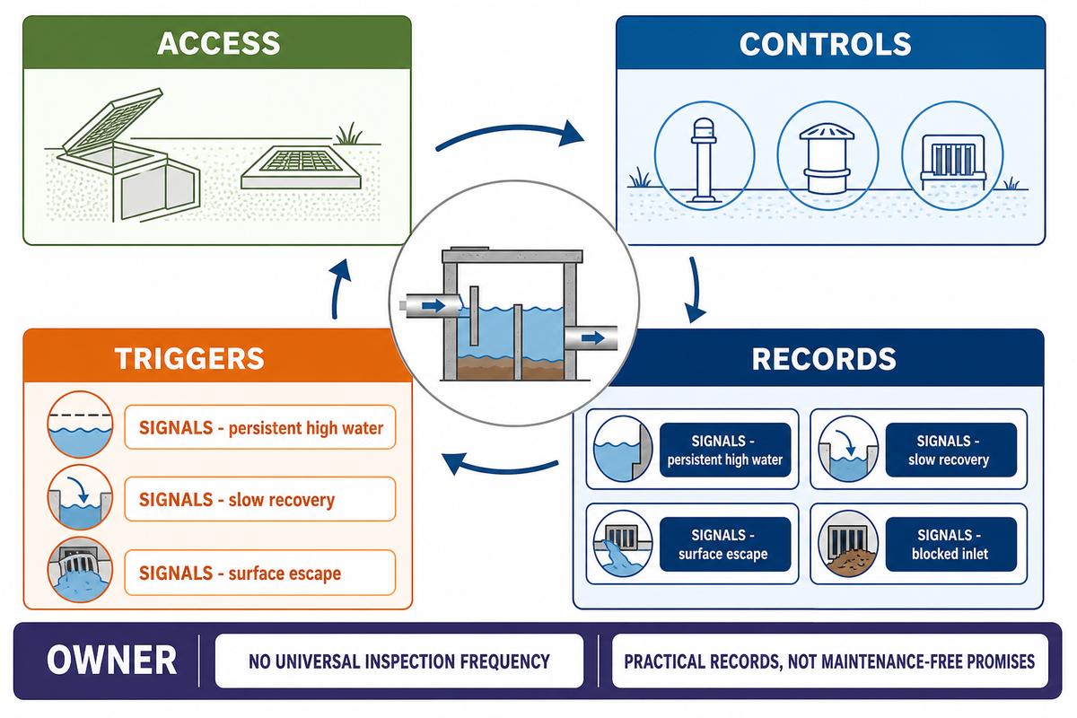
Prior to burial, measures pertaining to maintainability must be put in place. The current IWNL utility adoption guidance gives a jurisdiction-specific example that connects geocellular adoption with access, inspection, structural review, and silt-removal planning. The maintenance plan should name sediment sources, upstream controls, accessible inlets and outlets, inspection points, trigger events, cleaning routes, waste-handling arrangements, required records, and the responsible owner. Soakaway maintenance plans should record water levels during and after rainfall. A situation where controls are buried and storage space is hidden can still be inspected and assessed after hydraulic blockage, damage, or severe weather if access is designed before transfer.
Frequency of inspection can’t be uniform. Set it based on local needs and the source of runoff, the type of pretreatment, findings from commissioning, prevailing weather, unusual events, and performance. The maintenance plan should state what’s inspected, what evidence is recorded, what triggers cleaning or inspection, what actions are taken, and by whom, as well as how the system is returned to service.
| Signal | Possible cause family | Prevention or evidence | Do not assume |
|---|---|---|---|
| Slow drawdown | Restricted outlet, unsuitable infiltration, high groundwater, sediment | Level observations, outlet inspection, field and groundwater records | More crates will fix the route |
| Surface flooding | Blocked inlet, exceeded event, missing exceedance route, downstream restriction | Event record, inlet and control inspection, site flow-path check | The buried storage is the only cause |
| Sediment at controls | Weak pretreatment, construction contamination, missed cleaning | Accessible upstream assets and cleaning records | Stored volume equals clean usable volume |
| Settlement or distress | Formation, backfill, compaction, loading, or construction issue | As-built, hold-point, material, test, and load records | A module test identifies the site cause |
What happens when a soakaway fills up?
A soakaway is expected to store water temporarily while rainfall is continuing and after rainfall ceases. Persistent high water, slow recovery, or surface escape may indicate unsuitable infiltration, high groundwater, sediment, a blocked inlet, or an event beyond the design basis. Before a remedy is adopted, inspect the accessible part of the system and the evidence.
Maintenance records should include date, weather, and triggering conditions, observed levels, sediment condition, photos, cleaning, observed defects, and initiated corrective action. A practical record is more useful than a generic promise that a hidden system is “maintenance free.”
Request the Right Evidence Before Ordering

Keep each evidence class distinct in the procurement pack: product identity, factory quality records, independent product reports, company certificates, project calculations, approved drawings, installation inspections, and as-built records. Each item answers a different question. For example, the PD CEN/TS 17152-4:2025 structural-design scope concerns complete-system design evidence; it is not a substitute for a factory batch record or an as-built inspection record. An in-house compression test isn’t third-party certification. An in-house compression test is not third-party certification, and neither document replaces acceptance of the installed project system.
AQUA’s confirmed operations for moulded products comprise 30 injection-moulding machines and run on a two-shift basis. Working capacity for the core stormwater module range is approximately 1,000 m³ per day, with annual export volume around 300,000 m³. The timing and output for each model will vary based on the type of raw material, order mix, and the season; the figures noted don’t apply to the supporting materials that are procured.
Before shipment, owner-confirmed moulded-product batches use an approximately 2% sampling workflow covering dimensions, colour, appearance, and compression. An in-house compression testing machine is available at the factory; witness testing or a test video can be arranged when agreed. This sampling protocol doesn’t extend to every geotextile, geomembrane, or EPDM batch, and this internal testing isn’t considered an independent third-party certificate.
| Evidence | Owner or issuer | What it can support | What it does not prove |
|---|---|---|---|
| Factory batch record | Manufacturer | Recorded checks for the identified batch and scope | Independent certification or site design |
| Third-party product report | Named laboratory or body | The tested product, method, and declared conditions | Every configuration, load case, or installation |
| Company certificate | Named certification body | The certified management-system or company scope | Project-specific product performance |
| Project calculation and approval | Responsible designer and authority | The named site inputs, method, and accepted proposal | Conformity of hidden installed work |
| Hold-point and as-built record | Contractor and project verifier | Observed installation status and recorded deviations | Unrecorded future performance |
Use the 8-Point Shallow-System Readiness Gate
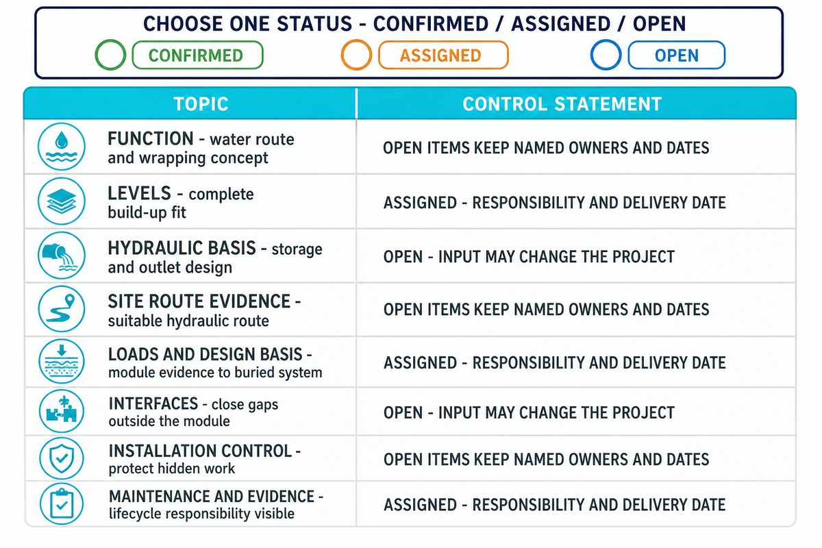
The 8-Point Shallow-System Readiness Gate is an AQUA planning construction framework and isn’t a regulation or industry standard. Confirm, Assign, or Leave Open each section. Product-fit review can start when unresolved items have named owners and dates; an Open item must never be converted silently into a supplier assumption.
Compare the checklist with the enquiry, then attach the controlling drawings and evidence. “Assigned” means a competent party has accepted the responsibility and a delivery date. “Open” means the input is still unclear and may change the route, volume, location, product configuration, evidence, construction, and price.
Shallow-system RFQ checklist — copy these into your quote request:
| Parameter category | Recommended range | Why it matters | How to verify |
|---|---|---|---|
| 1. Function | State attenuation, infiltration, or approved hybrid | Defines the water route and wrapping concept | Design brief and authority route |
| 2. Levels | Record elevations in mm or m on one datum | Tests whether the complete build-up fits | Current survey and coordinated drawing |
| 3. Hydraulic basis | State rainfall in mm and discharge in L/s or infiltration basis | Controls storage and outlet design | Named calculation method and input schedule |
| 4. Site route evidence | Record field, groundwater, pollutant, receiving-point, and approval status | Prevents an unsuitable hydraulic route | Reports, consent path, and designer review |
| 5. Loads and design basis | State cover in mm, load cases in project units, and design method | Connects module evidence to the buried system | Structural design input and responsibility record |
| 6. Interfaces | Identify every pipe, wrap, control, access, vent, and exceedance detail | Closes system gaps outside the module | Interface schedule and coordinated details |
| 7. Installation control | Name formation, pre-backfill, compaction, and as-built hold points | Protects work that will become hidden | Inspection and test plan with owners |
| 8. Maintenance and evidence | Name owner, access, triggers, records, and requested document scope | Makes lifecycle responsibility visible | Maintenance plan and evidence register |
A particularly useful resource is the shallow-system RFQ checklist, as this helps to simplify the handover process. Once the user controls the eight inputs, they should send the packet to the shallow geocellular drainage solution dedicated to project-specific shallow geocellular drainage for the configuration and the next steps in the commercial process. That page will continue to be the solution and inquiry product, and this document will continue to be the planning resource for education.
Key takeaway
A shallow geocellular project is ready for product-fit review when all 8 planning inputs are Confirmed, Assigned, or visibly Open with a named owner—never when missing site evidence has been converted into a module assumption.
Frequently Asked Questions
What is a shallow geocellular drainage system?
A shallow geocellular drainage system is a low-profile underground storage arrangement designed around restricted vertical space, with coordinated hydraulic, structural, access, construction, and maintenance interfaces.
The complete system includes modules plus its inlet, outlet or infiltration route, wrapping, pretreatment, access, surrounding construction, structural design, exceedance path, and maintenance plan. “Shallow” describes the available build-up or selected geometry; it is not one universal depth class. Site levels, groundwater, loads, water quality, approval, installation controls, and maintenance ownership still determine whether the arrangement is feasible.
What is the difference between a soakaway and an attenuation tank?
A soakaway infiltrates stored runoff into suitable ground, while an attenuation tank releases stored runoff at a controlled rate to an accepted receiving point through a flow control device.
Infiltration requires field, groundwater, pollutant, structural, setback, and approval evidence. Attenuation requires an accepted receiving point, discharge basis, flow control, and exceedance route. A controlled hybrid may combine both functions only when the local design method and authority accept it. Module geometry cannot choose among these routes, and a preferred option should remain provisional until its receiving path and approval basis are documented.
How deep should a shallow system be?
Shallow-system depth is project-specific; no single cover, excavation, or module depth applies to every site because levels, groundwater, loads, and the full construction build-up govern the usable envelope.
Align the inlet and outlet inverts, formation, groundwater, utilities, cover build-up, loads, wrapping, bedding, and local clearances on one datum. Confirm horizontal conflicts and the permitted construction envelope as well. The responsible designer then checks the named product and complete construction against the governing calculation method, project load cases, manufacturer information, and approval route.
What happens when a soakaway fills up?
Temporary storage filling during rainfall can be normal; persistent high water or surface escape needs investigation against drawdown, groundwater, inlet condition, and the approved exceedance route.
Check accessible inlets, outlets, pretreatment, sediment, observed groundwater, drawdown behaviour, rainfall conditions, and the design basis. Possible causes include blockage, unsuitable infiltration, high groundwater, downstream restriction, construction contamination, or an event beyond the design assumptions.
How long does an attenuation system last?
Attenuation-system life cannot be promised from a generic product category or one compression result because traffic loads, cover, groundwater, materials, joints, installation quality, inspection, and maintenance all affect service life.
The project design should define its design-life basis and connect the named material, long-term loading, load duration, cover, soil, groundwater, chemical exposure, joints, penetrations, surrounding interfaces, and boundary conditions. Construction quality then affects whether the installed work matches that basis. Ask the supplier and responsible designer which documents support the exact model, configuration, factors, and calculation. Establish accessible inspection points, maintenance triggers, responsible ownership, and record retention. Preserve factory records, approved drawings, hold-point evidence, as-built information, inspections, cleaning actions, and changes so later reviews address the actual system rather than an assumed universal lifespan.
What information should a buyer send for review?
A buyer should send the eight readiness inputs, current drawings, named evidence requests, and an open-item register so the supplier can separate product-fit questions from the project designer’s approval duties.
Include function, coordinated levels, hydraulic basis, route evidence, load and design basis, interfaces, installation controls, and maintenance ownership. Mark each item Confirmed, Assigned, or Open, then identify the owner and closeout date for every unresolved item. Add the requested product configuration, report scope, packing, delivery, and support needs, while keeping project design and installation acceptance with the responsible parties.
Why AQUA Publishes This Planning Guide
For international projects, AQUA Rain Water separates geocellular stormwater and shallow attenuation product supply from hydraulic design, installation, and approval responsibility. AQUA Rain Water supplies geocellular stormwater modules and shallow attenuation products for international projects, so incoming enquiries often cross product, site, design, and installation boundaries. This guide makes the boundaries clear before the configuration review and keeps factory evidence and project approval separate.
References & Sources
- How to comply with sustainable drainage systems standards Natural Resources Wales
- Approved Document H: drainage and waste disposal UK Government
- Managing rainwater using infiltration and soakaways Cardiff Council
- Green infrastructure and groundwater protection United States Environmental Protection Agency
- Infiltration facilities and underground injection control guidance Oregon Department of Transportation
- Subsurface infiltration trench Philadelphia Water Department
- Subsurface infiltration practice manual Philadelphia Water Department
- PD CEN/TS 17152-4:2025: guidance for structural design of modular systems BSI
- A study on the structural performance of geocellular modules Journal of Civil Engineering, Science and Technology, Universiti Malaysia Sarawak
- Geocellular storage systems Susdrain
Turn the Guide Into a Project-Specific Review
Please send AQUA Rain Water controlled levels, hydraulic basis, site-route evidence, load cases, interface schedule, installation responsibilities, and the desired scope and extent of documentation. For projects in England, the GOV.UK Approved Document H page is one jurisdiction-specific starting point; every project must still use its applicable authority route. We’ll be able to review the proposed product configuration and determine the remaining open commercial or technical inputs.