Get in touch with AQUA Company
Shallow Attenuation Tank for Geocellular Drainage Systems
A shallow geocellular drainage system begins with a simple constraint: there is not enough useful depth for a conventional deep tank. With this in mind, AQUA provides four low-height modules. This allows engineers and project buyers to review storage and footprint along with the hydraulic configuration; AQUA also requests specific reviews on a model-by-model basis.
85–250 mm
Four single-module heights
1000 × 500 mm
Common unit footprint
95%
Recorded void ratio
40.375–118.75 L
Calculated storage per module
Shallow Storage for Depth-Constrained Sites
For an 82 mm sub-base drainage layer, review the separate product: Geocellular Sub-base System. An 82 mm cellular layer for shallow sub-base drainage and project-specific component layouts. This is a separate product family from the 85–250 mm shallow attenuation tanks.
The useful comparison is stored volume versus available construction depth, not height alone. A shallow tank may reduce the storage layer depth, but it is not automatically the lowest-cost or lowest-risk answer once excavation, cover, groundwater, outlet control and maintenance access are considered.
The common failure is a one-variable choice. An 85 mm layer can solve a depth problem yet still fail the storage or cover review because plan area, loading and hydraulic function are separate inputs. AQUA Rain Water provides the four-height comparison and model documents; the project designer resolves the installed-system risk.[5]
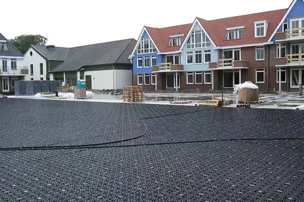
Drainage layer
- Confirm the collection path and discharge point.
- Define the surface and surrounding build-up.
- Review sediment interception before burial.
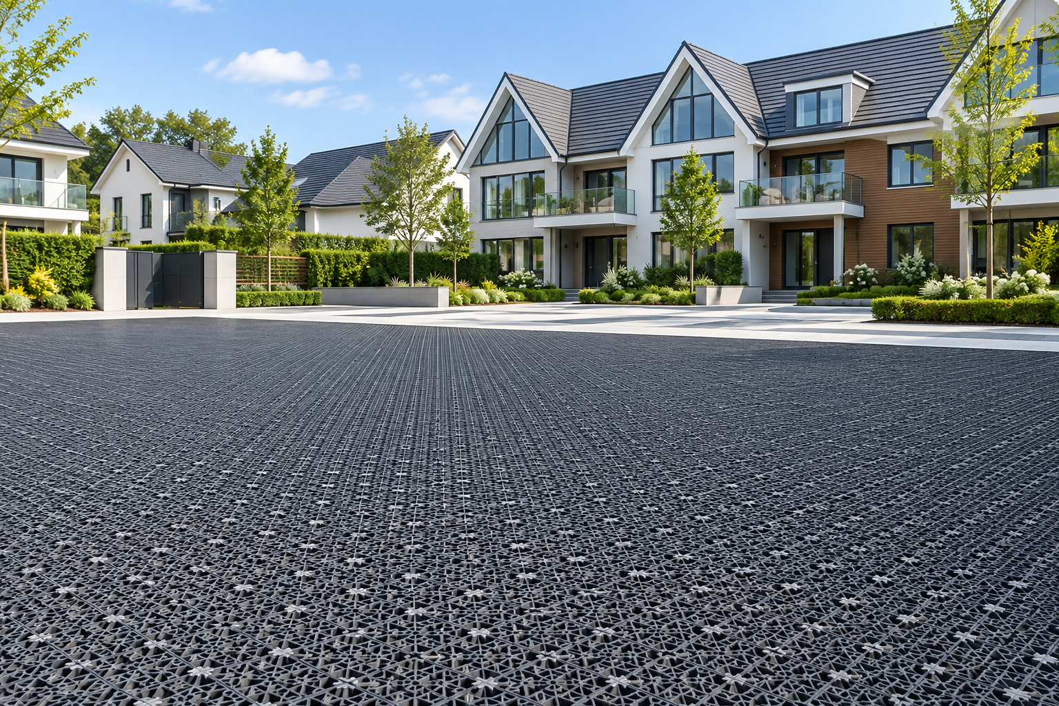
Infiltration system
- Check soil infiltration evidence and groundwater.
- Specify the project geotextile interface.
- Keep an overflow or exceedance route in the design.
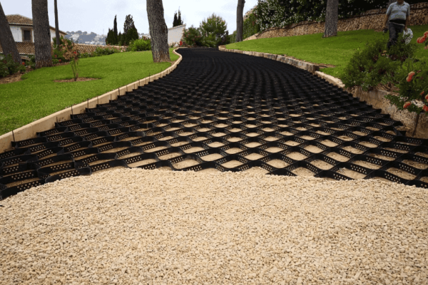
Lined attenuation
- Define storage volume and allowable discharge.
- Specify geomembrane and protection geotextile.
- Coordinate inlet, outlet and flow-control details.
Selection note: treat module geometry and storage as the first decision, then verify structural, hydraulic and maintenance inputs for the complete buried system.
Have a depth limit? Compare all four models before fixing the excavation profile.
ARW-SA Models and Verified Storage Data
Each model uses the same plan footprint and changes the storage layer with height. Storage values below have been calculated from external dimensions and multiplied by the 95% void fraction; two modules cover one square meter of plan area.
Use the table for product quantity and plan area comparison. Complete-system selection still requires a project review of cover, lateral actions, loading, backfill, subgrade, groundwater and connection details.[2]
| Selection field | ARW-SA-85 | ARW-SA-150 | ARW-SA-200 | ARW-SA-250 |
|---|---|---|---|---|
| Length | 1000 mm | 1000 mm | 1000 mm | 1000 mm |
| Width | 500 mm | 500 mm | 500 mm | 500 mm |
| Height | 85 mm | 150 mm | 200 mm | 250 mm |
| Void ratio | 95% | 95% | 95% | 95% |
| Calculated usable storage | 40.375 L | 71.25 L | 95 L | 118.75 L |
| Units per square metre | 2 | 2 | 2 | 2 |
| Material | 100% recycled PP | 100% recycled PP | 100% recycled PP | 100% recycled PP |
| Standard colour | Black | Black | Black | Black |
-
Calculate modules
Divide required nominal storage in litres by the chosen model’s per-module storage, then round up to a whole module.
-
Calculate plan area
Divide the rounded module count by two for a single-layer plan-area estimate before allowances and layout constraints.
-
Review the system
Check stack arrangement, cover, surface loading, subgrade, backfill, groundwater and access with the responsible project designer.
Need a traceable quantity estimate? Produce the arithmetic before sending the project enquiry.
Estimate module quantityHydraulic Configurations for Drainage, Infiltration and Attenuation
The same module geometry does not create the same hydraulic system. Surrounding soil, groundwater and the discharge route control whether water infiltrates, is stored for controlled release, or moves through a drainage layer.[3]
Use the project-specified geotextile and confirm soil infiltration, groundwater separation, pretreatment and overflow provisions.
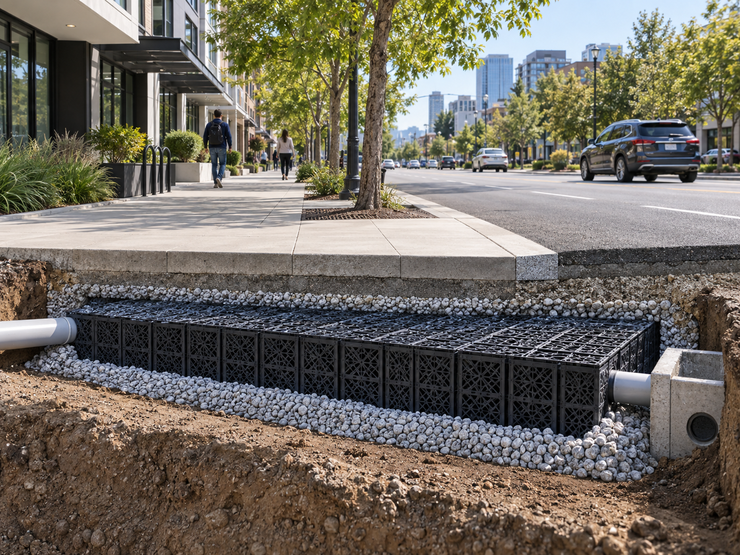
Use the project-specified geomembrane with protection geotextile and coordinate the controlled outlet with the drainage design.
Define the collection zone, route to the downstream network and the interface with channels, inlets or outlets.
Sustainable urban drainage systems (SuDS) are a form of sustainable drainage in which rainwater from impermeable areas becomes surface water runoff. Underground storage can store water, including excess water during heavy rainfall, reduce peak flow and support flood risk management.
A flow control device sets the discharge rate to a sewer, watercourse or downstream stormwater drain. The designer selects an orifice, throttle or vortex flow control where needed; a vortex is an outlet option, not a feature inside the module.
Trafficked car parks require a heavy-duty pavement specification matched to ground conditions and the water storage layout. Geocellular attenuation tanks remain one part of the wider stormwater and water management design.
Module Assembly and Project Connections
AQUA offers a one-piece, modular upper and lower panel system that snaps together. Individual modules are joined by interlocks.[2] It is a common misconception that the number of pipes, openings, or connections per order can be used to estimate the total number of openings or connections in a drainage system.
Unit assembly
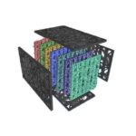
Upper and lower moulded panels connect around internal supports. The completed unit is not intended to be reopened.
Horizontal layout
Separate interlock connectors join adjacent modules. Connector quantity is confirmed against the supplied layout and model.
Vertical arrangement
Modules can be stacked, while the correct single-height model is preferred where it meets the required layout and design inputs.
Pipe interface
Pipe or open-channel connections are project-specific and normally completed on site against an approved drainage detail.
Supply and Lead Time Planning
Production runs are scheduled at approximately 15 days, subject to ordered model, material preparation, order mix and season. The project review should therefore close the model, quantity, wrap, accessories, connection needs and document package before the production schedule is treated as fixed.
Send project inputs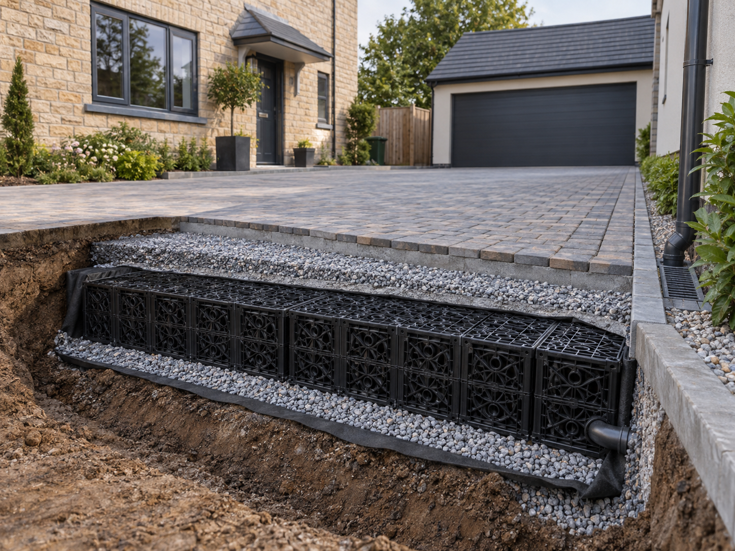
- Required effective storage and permitted construction depth
- Site plan, available footprint and proposed module arrangement
- Drainage, infiltration or lined attenuation role
- Surface use, design loading, cover build-up and subgrade information
- Groundwater, soil data, inlet, outlet and flow-control requirements
- Inspection access, silt-control and maintenance concept
- Destination, shipment preference and required product documents
- Full-container shipment is preferred for core modules.
- For suitable orders, LCL and smaller-container shipments can be reviewed.
- Core module bodies and side panels are normally palletised.
- Per order, clips, flange covers, and smaller accessories are packed either in wooden cases or bags.
Batch Inspection and Supporting Documents
Before shipment, our core moulded-product batches use approximately 2% sampling covering dimensions, colour, appearance and compression. This is an internal batch-check workflow, not automatically a statistical acceptance plan and not a third-party certification.
Geotextile and geomembrane are supporting procured products coordinated through Aqua’s supply process. The moulded-product sampling statement is not extended to every procured geotextile, geomembrane or EPDM batch.
Internal checks
We review the ordered configuration, visible condition, inspection status and packing before loading.
01Compression capability
Our factory has a compression testing machine for internal or witnessed testing of core moulded-product batches.
02Order documents
Selected third-party product test reports and company certificates can be provided according to the product and order.
03Want the evidence matched to the order? Ask for the model, batch-inspection and available document list with the quotation.
Request document scopeFrom Product Configuration to Export Packing
Service coordination for product selection, batch inspection, supporting materials, export packing, loading supervision, technical support, and the procurement of geotextiles and geomembranes can be arranged. This service reduces the risk of ordering a storage volume without confirming the wrap, accessories, supporting materials, documents or shipment method.
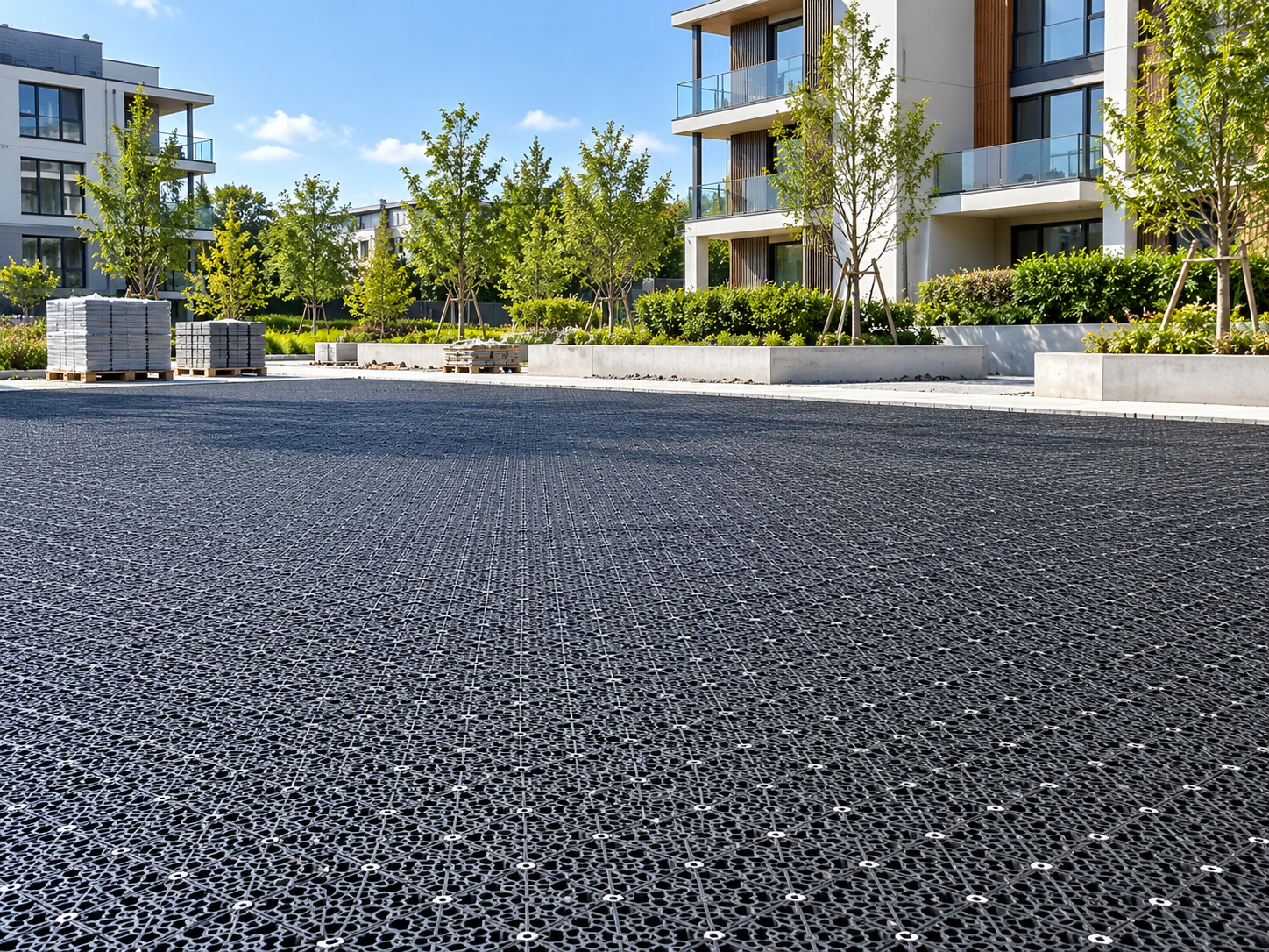
Pavement & Buried-System Design
Road and parking applications require the responsible engineer to verify the complete pavement and buried-system design.
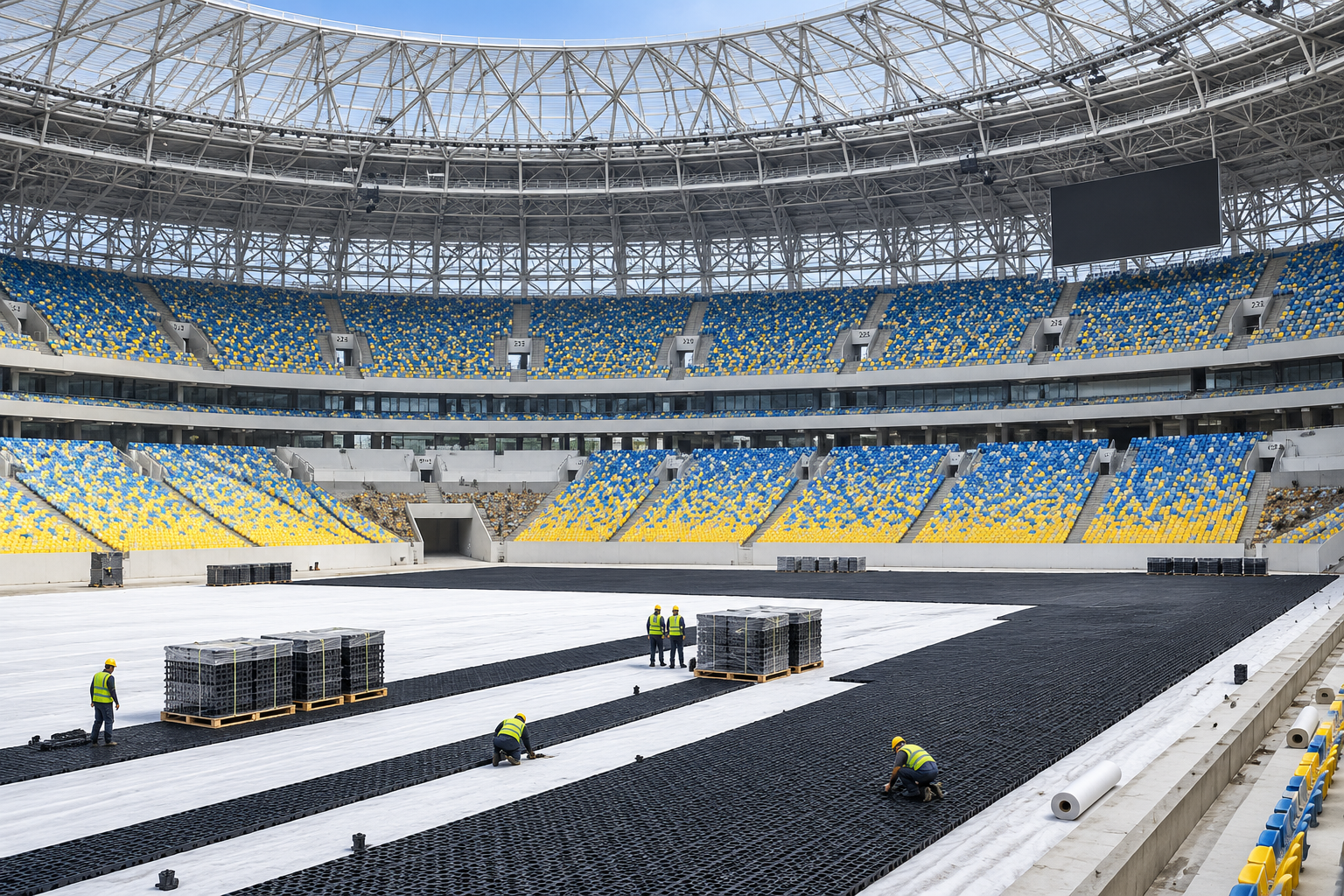
Usable Surface Protection
Low-height drainage or storage can protect usable surface levels where the hydraulic route is designed around the site.
01
Input review
We map depth, storage, footprint, hydraulic role and project interfaces.
02
Model proposal
We compare the four ARW-SA heights and confirm the quoted supply scope.
03
Production
We schedule the moulded model and ordered configuration against material and order mix.
04
Inspection
We review applicable moulded-batch checks, product configuration and packing status.[4]
05
Loading
We can arrange loading supervision, container securing, sealing and photographic reporting.
PRODUCTION & FACILITY CAPABILITY
Factory Capability for Core Moulded Modules
Our factory was established in 2009 and supports the core stormwater-module range with 82 injection-moulding machines and two-shift production. Working capacity is approximately 100,000 m³/month for core modules, while annual export volume is approximately 1,000,000 m³/year; actual timing remains dependent on model, material, order mix and season.
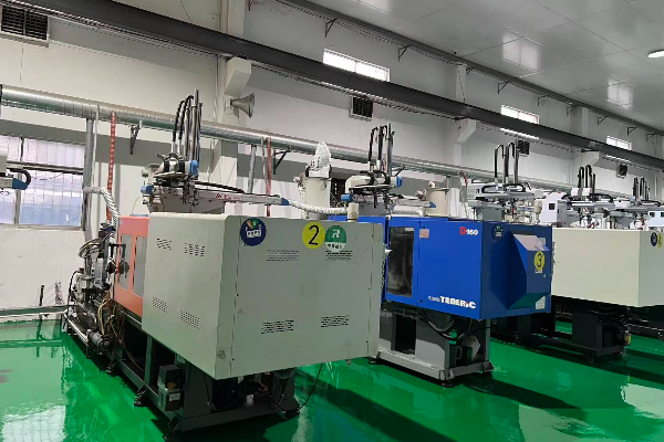
Model control
We configure moulded products according to the ordered model and agreed supply requirements.
Witness options
We accept customer or third-party factory audits by prior appointment and can arrange remote video inspection.[4]
Loading review
We can supervise appearance and dimension checks, packing, container securing, sealing and photo reporting.
Confidentiality
We do not disclose customer or distributor identities; names are published only when specifically approved.
Application Fit and Trade-Offs
For projects with a controlling constraint of limited depth and a design that allows a modular approach, shallow geocellular storage systems can be considered. The cheapest option is not always the best route; the shallowest model is not always the smallest system.
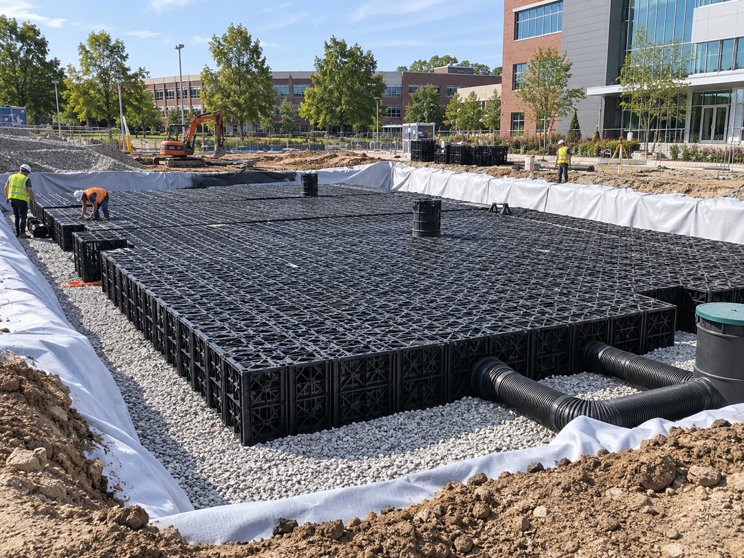
Good fit
- Podiums, plazas, landscaped areas and sports turf with tight depth
- Distributed drainage or storage zones around utilities
- Projects needing a four-height storage comparison on one footprint
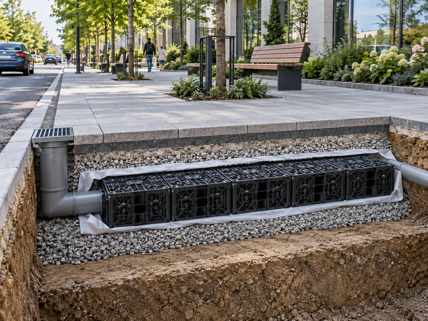
Review closely
- Traffic loading, shallow cover or unusual surface build-up
- High groundwater, buoyancy exposure or weak subgrade
- Limited inspection access, heavy silt load or complex connections
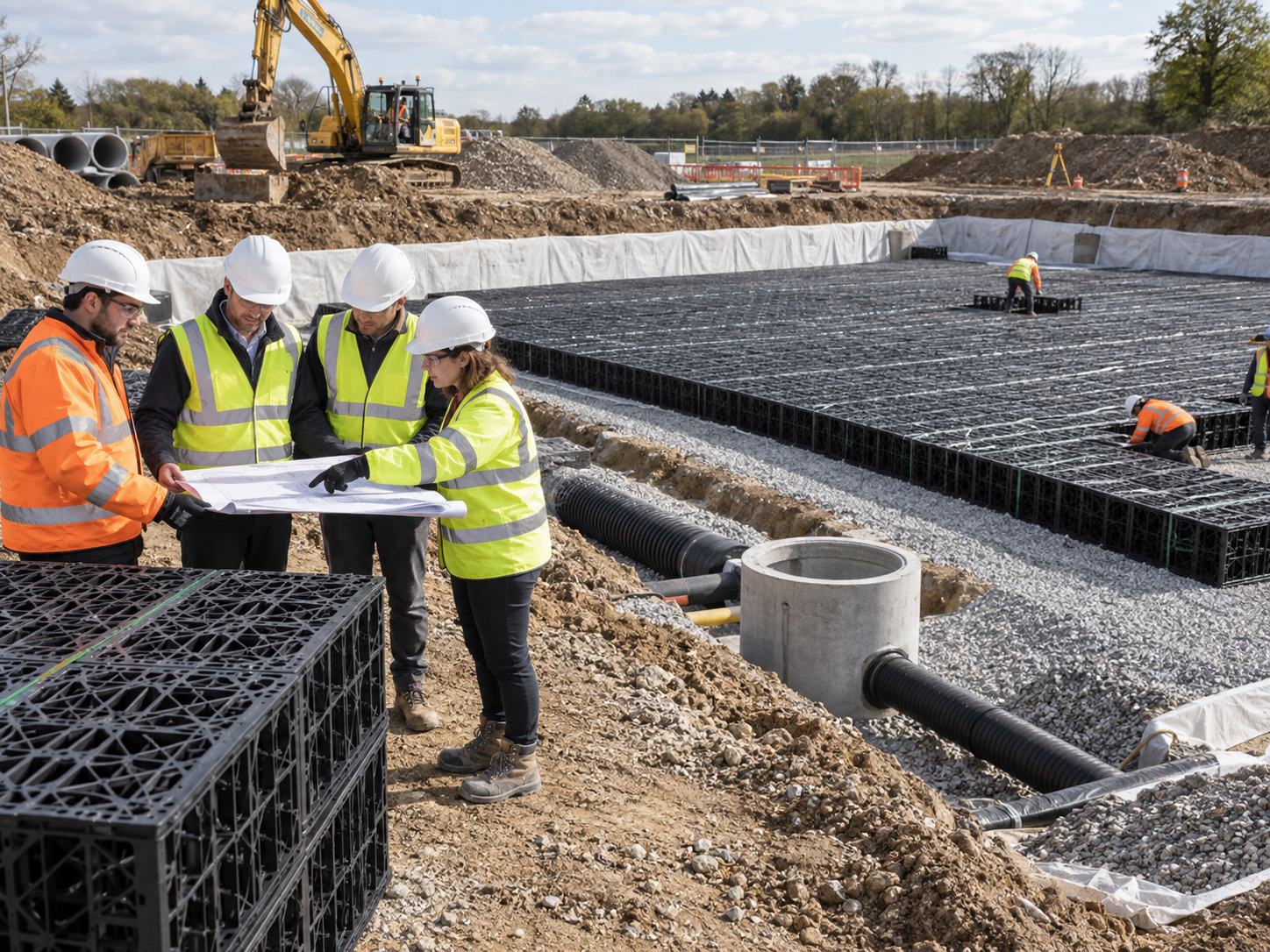
Compare alternatives
- Very large storage where another structure improves constructability
- Sites where cleaning access controls the whole system
- Projects without confirmed discharge, infiltration or maintenance responsibility
Shallow Geocellular Drainage Engineering Tools
Select an engineering utility below to configure your shallow stormwater storage system, estimate module quantities, or prepare project specifications.
ARW SA Depth to Storage Selector
Calculate the required storage volume based on excavation depth limits and site catchment area constraints.
Shallow Tank Module Quantity Estimator
Estimate the precise number of geocellular modules and footprint needed to achieve your target storage capacity.
Shallow Geocellular RFQ Checklist
Ensure all critical site conditions, load ratings, and technical requirements are prepared before submitting a quotation request.
Frequently Asked Questions
Which shallow tank heights are available?
85, 150, 200 or 250 mm.
How much water does each module store?
Calculated usable storage is 40.375 L for ARW-SA-85, 71.25 L for ARW-SA-150, 95 L for ARW-SA-200 and 118.75 L for ARW-SA-250. These values use external dimensions multiplied by the recorded 95% void ratio.
Can the modules be used as shallow soakaway crates?
They can form an infiltration configuration when the project specifies a suitable permeable geotextile interface and confirms soil, groundwater, pretreatment and overflow conditions. Infiltration is not always permitted or appropriate, so local design review remains necessary.
What changes for an attenuation tank?
A lined attenuation configuration uses the project-specified geomembrane with protection geotextile and a designed outlet or flow-control route. Confirm the required storage, allowable discharge, outlet level, overflow route and inspection concept before quoting the product configuration, because the module quantity alone does not set the hydraulic performance.[3]
Can the shallow modules be installed beneath traffic?
Traffic suitability depends on the complete system, including model, cover, pavement build-up, surcharge, stack height, backfill, subgrade and installation quality. Ask for model-specific document review, supply the expected traffic category and construction section, and have the responsible engineer approve the buried-system design.
Are compression test figures the same as allowable project load?
No. Component results do not create a universal project rating.
How are modules connected?
Upper and lower panels snap together to form a unit, while separate interlocks connect adjacent modules horizontally. The final connector quantity and stack arrangement are confirmed against the project layout.
How are pipes connected?
Against the approved project drainage detail, normally on site.
What does the approximately 2% inspection cover?
It covers sampling of core moulded-product batches for dimensions, colour, appearance and compression before shipment. It is a first-party batch-check workflow, not a published AQL acceptance plan, a declaration that every module is tested, or a rule for every procured geotextile, geomembrane or EPDM batch.
Can buyers witness factory checks?
Yes, when the scope is agreed in advance. Test video is another option.
How long is production?
Production runs are scheduled at approximately 15 days, subject to ordered model, material preparation, order mix and season. Close the model, quantity, accessories and document requirements first; the quotation then confirms timing for that reviewed configuration rather than treating the general schedule as a guaranteed dispatch date.
Does AQUA install the system?
No. AQUA supplies the product and related support.