Get in touch with AQUA Company
How to Specify a Shallow Geocellular Sub-base System
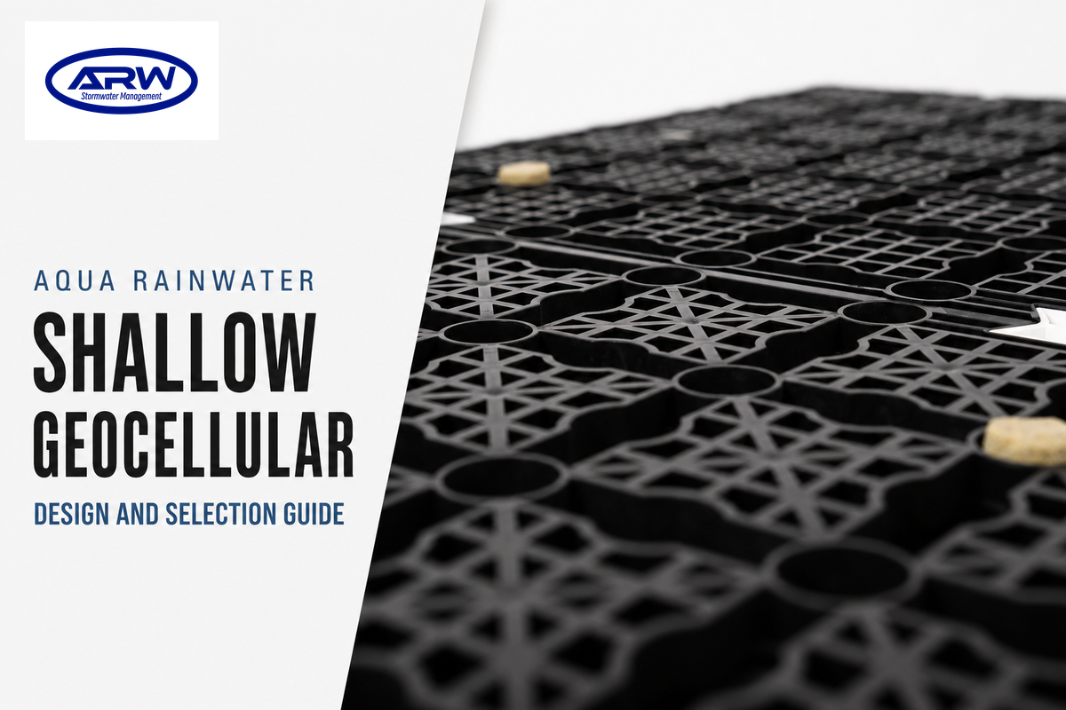
A shallow geocellular sub-base system is a load-bearing pavement layer that can provide temporary water storage within narrow excavation spaces. It isn’t a stand-alone drainage solution on its own. Defensible selection combines the hydraulic route, pavement design, construction, maintenance, and assessment of access prior to selection of a module.
Key takeaway
Choose the whole drainage and pavement system first. Module depth, void space and compressive data only become meaningful after the site route, loads, interfaces, exceedance path and maintenance access are defined.
What does a shallow geocellular sub-base system do?
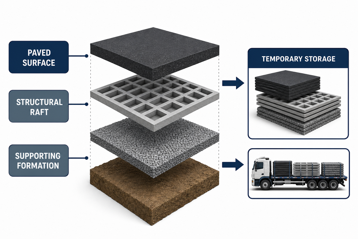
A geocellular sub-base creates a structural raft beneath a paved surface. Part of the raft can be used for water storage or conveyance. Any decrease in the depth of aggregate layers and buried storage needs project-specific verification and doesn’t remove the need for treatment, control of outlets, or analysis of the structure.
A 2025 academic review discusses the hydraulic and structural functions and describes limited understanding of short term and long term structural behavior within its review scope. Vertical traffic loads and lateral actions from backfill and water affect the system. Because of this, a declared cell strength can’t approve a pavement system on its own. Treat a description such as high-strength structural sub-base replacement as a claim to verify, not a traffic rating. A geocellular sub-base replacement system needs evidence for the sub-base layers it replaces and the loads it transfers. Blue-green roofs, green roof drainage and podium landscapes need their own design review; a roof detail does not establish performance beneath a trafficked hardscape. As a roof-specific example, GSA planted-roof guidance discusses waterproofing and retained-water loads; it is not evidence of pavement-system approval.
This system, as it currently stands, can’t achieve all of the necessary sustainable drainage outcomes on its own. In a SuDS strategy, water-quality treatment, source control, amenity and biodiversity are normally reliant on upstream and surface components. The geocellular layer is one of many elements of a treatment train; it isn’t the treatment train as a whole.
Go or no-go: is shallow storage the right response?
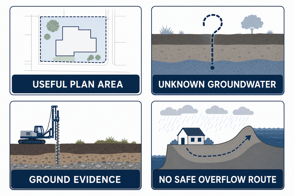
Low module height is useful only when the total installed profile fits and the site can support the desired route. For context, England’s SuDS standards address structural integrity, failure scenarios and maintenance access; they do not approve a shallow storage system for a particular project. Screen the project before sizing: excavation constraints, utilities, groundwater, available footprint, formation condition, traffic, discharge consent, infiltration evidence and adoption rules can each affect the answer. For a UK screening pass, compare the seasonal high water table, geology and percolation data with flood risk, climate change allowances, the receiving watercourse and any downstream pond or basin; the NPPF and national planning policy framework may frame planning expectations, but project evidence must still address excess water, erosion and instability.
Screen pollution risk during site selection. England’s standards identify refuelling, washing and hazardous-material areas as potentially needing separate containment or treatment; storage capacity alone does not make those flows suitable for infiltration. Confirm the applicable discharge and permission route locally. The proceed/pause checklist below is an editorial concept-screening aid, not a standard or engineering approval threshold; project designers and local authorities determine acceptance.
Proceed to concept design when
- Available plan area can offset limited depth
- Formation and groundwater evidence are available
- The outlet or infiltration route is credible
- Traffic and pavement responsibilities are assigned
Pause or compare alternatives when
- Seasonal groundwater is unknown
- Utilities break the storage footprint into unusable fragments
- No safe overflow route exists
- Cleaning points cannot be reached physically
Deeper attenuation storage is an illustrative option to assess for a limited footprint when the project permits excavation. Conventional aggregate sub-base is another illustrative option to assess for a pavement where there’s no need for water storage. Shallow, dispersed storage has merit when it solves a real space or hydraulic constraint without leaving behind an uninspectable asset.
Decide the hydraulic route and treatment train first
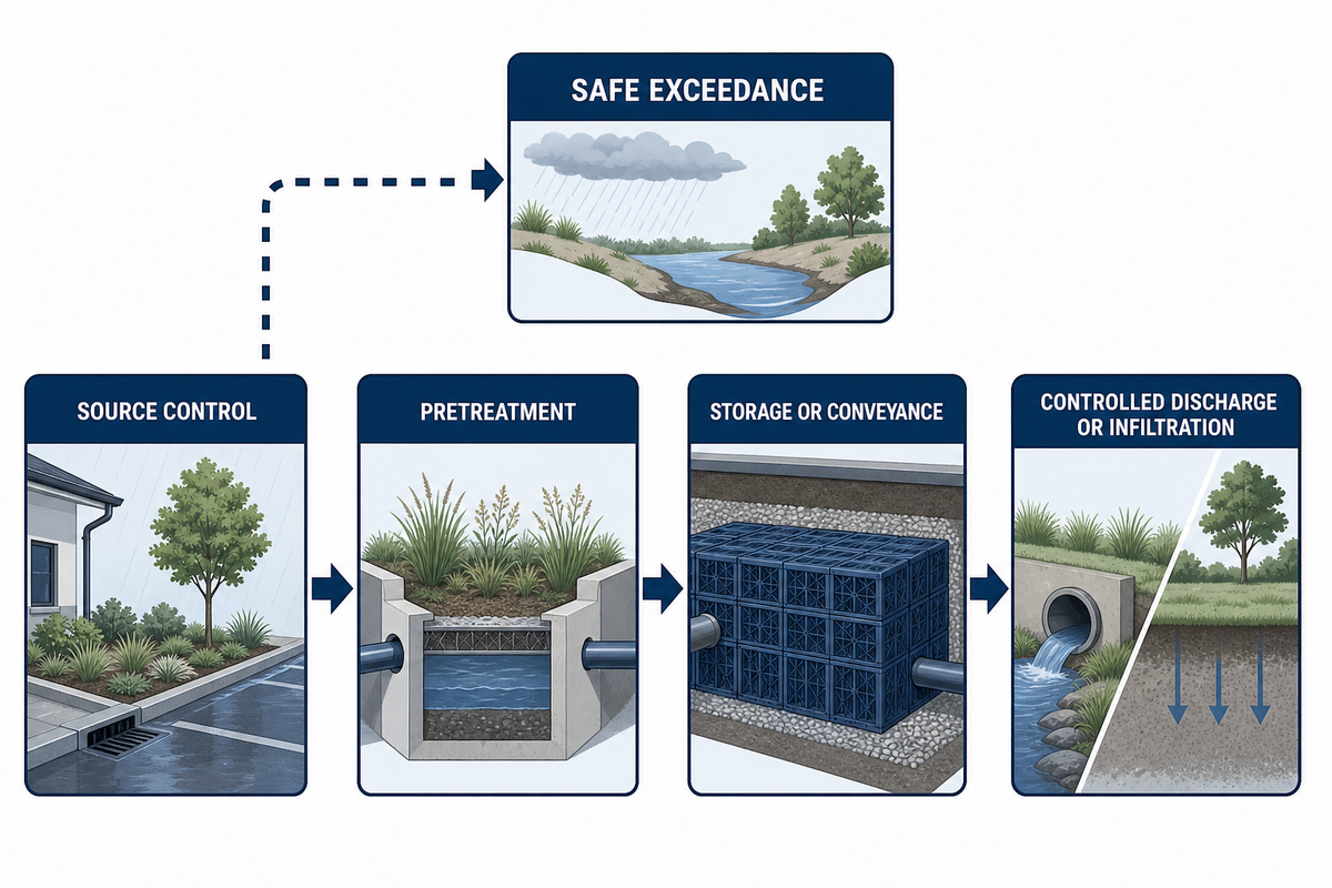
Identify the path that runoff takes when it lands and when it can safely go during regular and extreme scenarios. The path should show source control, pretreatment, storage or conveyance, controlled discharge or infiltration, surface exceedance, and overflow. Compare geocellular tanks or a crate-and-membrane assembly with other surface water drainage options; decide whether the on-site system will hold water for irrigation, reduce water discharged downstream, or mitigate peak flow. Only then can the position of the modular cells be decided. A soakaway is an infiltration destination; its suitability depends on the receiving ground and groundwater conditions. A surface water management system needs a defined entry point as well as attenuation capacity. For example, impermeable asphalt can direct rainwater to inlets, while permeable paving admits it through the pavement. Draw the outlet throttle and the response to blockage on the same sketch. This makes the failure route visible before an inaccessible storage system is selected. Route selection also interacts with site layout, contamination, biodiversity and amenity; it is not an isolated hydraulic decision. Include adjacent-site inflows and identify how blockage will become visible at the surface.
Because an inappropriate practice can cause resource impacts, approval issues and wasted cost, select guidance uses a treatment-train approach. For a geocellular sub-base, this means sediment exclusion, definition of water entry and exit, and examination of the result of surcharged outlet. The five steps below are a suggested concept-design sequence synthesized for this guide, not a prescribed regulatory or approval process.
- Map runoff sources — separate clean pavement runoff from flows that need additional treatment.
- Choose the route — decide between attenuation, infiltration or a controlled combination.
- Protect the storage — position pretreatment and silt controls before inaccessible voids.
- Define the outlet — state control level, discharge destination and surcharged condition.
- Draw exceedance — show where water travels safely when the design event is exceeded.
Which inputs are needed for preliminary sizing?
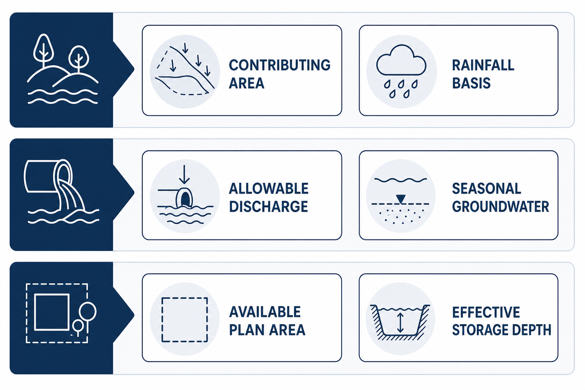
An approximate sizing estimate requires water balance and measurement, not a catalog volume. Record the contributing area, rainfall basis and climate allowance, off-site inputs, allowable discharge, infiltration evidence, seasonal groundwater, available plan area, effective storage depth, and declared void space. Use the declared void ratio only for the selected configuration. The final volume should be checked in the project drainage model or an alternative calculation method accepted for the project and jurisdiction.
For a rough storage check, the approximate volume can be calculated as plan area × effective storage depth × void ratio. Compare this result with the calculated storage volume after inflow, permitted outflow, and infiltration constraints are applied. This relationship is a screening calculation, not a final drainage design. High-void cells provide void space for water storage, but usable attenuation capacity depends on operating levels and connected volume. An ultra-shallow attenuation tank with an outlet above its lowest voids cannot assume that all of its nominal depth drains freely. Identify that inactive volume in the calculation instead of substituting a catalogue capacity.
For infiltration, measured rates may require a documented reduction for construction impacts and long-term decline. For example, Minnesota guidance applies a factor of 2.5 for compaction and sedimentation; this is a jurisdiction-specific example, not a universal design factor.
| Input | Why it matters | Evidence to request |
|---|---|---|
| Contributing area | Sets incoming runoff | Drainage plan |
| Rainfall and climate allowance | Defines the design event | Approved criteria |
| Allowable discharge | Controls required attenuation | Consent or authority note |
| Seasonal groundwater | Affects infiltration, drainage and buried-system assessment | Monitoring or investigation |
| Infiltration performance | Controls emptying time | Field testing and adjustment basis |
| Surcharged outfall | May prevent gravity discharge | Network level assessment |
| Available footprint | Converts volume into plan area | Coordinated utility plan |
| Effective storage depth | Links geometry to storage | Approved layout |
| Declared void space | Avoids gross-volume assumptions | Product documentation |
Why is structural acceptance a system question?
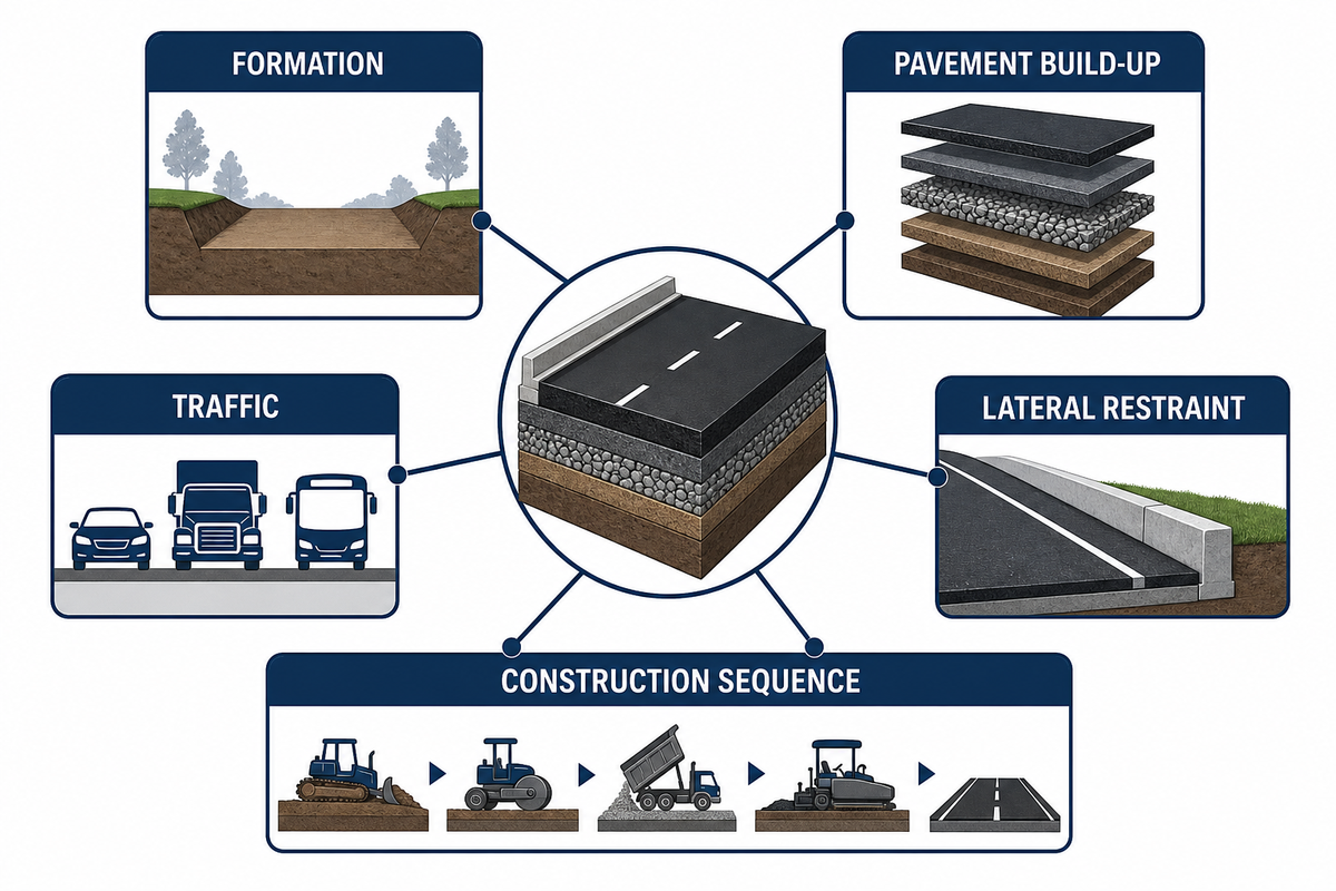
Structural acceptance lies with the entire assembled pavement system and not with a single modular cell. Therefore, a claim for sub-base replacement posits a system level burden of proof. The designers concerned should provide formation bearing, aggregate layers, cover and surfacing, traffic, extraordinary loads, repeated loading, lateral restraint, settlement control, joints and construction sequence.
Hydrologic and structural sizing should be completed as separate checks, with the governing build-up carried into the coordinated design.
Ask who accepts the formation and who verifies the pavement and who checks the connections and who approves exceptions. Include, where relevant, ordinary vehicles, emergency vehicles and construction plant. Settlement control and the assessment of long-term deformation are recommended. Evidence of settlement shouldn’t be based on a single short-term compression value. For a permeable paving sub-base, Minnesota guidance discusses soil strength expressed as California Bearing Ratio, alongside other measures. CBR data belongs to the formation assessment; it is not a module load certificate. A traffic-rated claim, especially for heavy traffic loads, still needs the selected pavement build-up and loading conditions. Treat subbase replacement as a coordinated design change, not a material-name substitution. The BSI summary of PD CEN/TR 17179:2018 describes reservoir installation guidance but excludes road-base and road-sub-base details. Installation compliance therefore cannot stand in for pavement design acceptance.
How do shallow cells compare with aggregate and deeper storage?
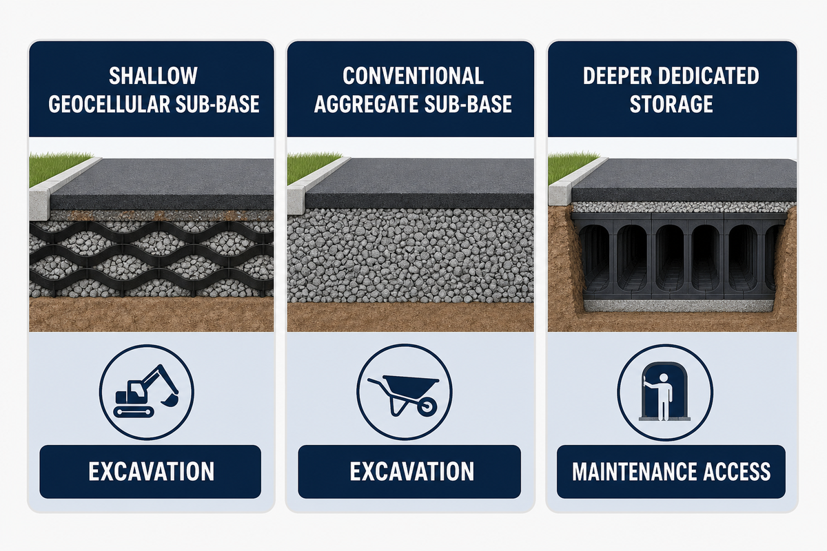
As far as possible, a comparison should be based on the same scope and performance specifications. Compare excavation and pavement function, storage, treatment and controls, construction, access, replacement, and maintenance. The price of the module isn’t the only determining factor. Also compare surface-led measures such as swales or bioretention where the site permits. Underground storage can complement these features; assess the opportunity to manage runoff near the surface before committing the whole duty to buried cells.
The three option rows below are illustrative concept comparisons, not general engineering findings or suitability decisions.
| Option | Possible best-fit condition to assess | Main constraint |
|---|---|---|
| Shallow geocellular sub-base | Limited depth, useful plan area, combined pavement and storage role | Interface control and buried access |
| Conventional aggregate sub-base | Straightforward pavement with no high-volume storage duty | Check configuration-specific usable void space |
| Deeper dedicated storage | Compact footprint and adequate excavation depth | Depth, access and separate pavement layers |
EPA’s archived cost guidance distinguishes initial from life-cycle costs (planning, design, installation, operation, maintenance, and replacement costs). It also highlights that comparison of costs only may conceal performance differences. Apply this definition to case studies on project options without fabricating hypothetical savings. In an illustrative comparison, place the same runoff duty, pavement service and maintenance access beside each option. Include excavation, gravel layers, disposal, outlet works and replacement access in the cost scope. Fewer aggregate deliveries may change environmental impact, but a benefit claim needs a project inventory and defined comparison boundary. AQUA RainWater’s geocellular attenuation tank guide explains the separate buried-storage brief.
Which installation interfaces must be inspected?
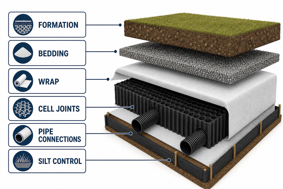
Before covering, suggested coordination topics include the formation, bedding, placement of geotextiles/geomembranes, modular cell joints, penetrations, inlets, outlets, silt control systems, edge restraint, and build-up and cover systems. When installing a proprietary module such as a specified Permavoid product, follow its manufacturer-specific drawings and keep the trade name distinct from generic acceptance criteria. Use the current installation guide, approved drawings, project inspection plan and local acceptance rules to define actual hold points, who inspects each detail and who releases the work for covering.
Check levels and falls against the approved layout. Take photos and note the location. Restrict impermissible materials from the worksite, block silt ingress, and record each approved deviation. This includes the structural raft. A clean transfer of the works begins while the structural raft is still visible. Where pipes and cables interrupt the layout, record the actual penetration detail. Choose geotextile or geomembrane functions from the drainage route; AQUA’s geotextile guide explains separation and filtration checks. STEP guidance on underground infiltration systems discusses inspection before backfilling, including levels, fabric and pipe connections; the approved design and local acceptance requirements govern the project. If the inspector finds a pipe elevation that differs from the approved drawing, record the mismatch and obtain a design disposition before hiding the connection.
What belongs in a Pre-Cover Evidence Pack?
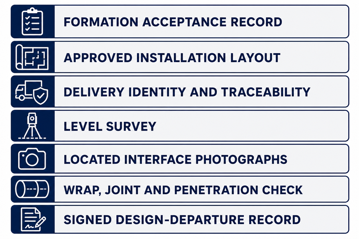
The Pre-Cover Evidence Pack is a seven record checkpoint for work that will soon be concealed. It organizes acceptance evidence; it isn’t certification and doesn’t demonstrate whole-life hydraulic or structural performance. This guide groups the records into seven suggested files, drawing on construction and commissioning themes in England’s SuDS standards; the standard does not prescribe this pack.
- Formation acceptance record
- Approved installation layout
- Delivery identity and traceability
- Level survey
- Located interface photographs
- Wrap, joint and penetration check
- Signed design-departure record
Keep test results, product declarations, calculations, and commissioning records in their respective project files. The pack answers the question “what was checked before covering?” Agree the asset owner, maintenance access and rehabilitation or replacement plan separately before handover. Those whole-life responsibilities need their own project records. It can’t answer “how will the asset perform throughout its intended service life?”
How should inspection and maintenance access be tested?
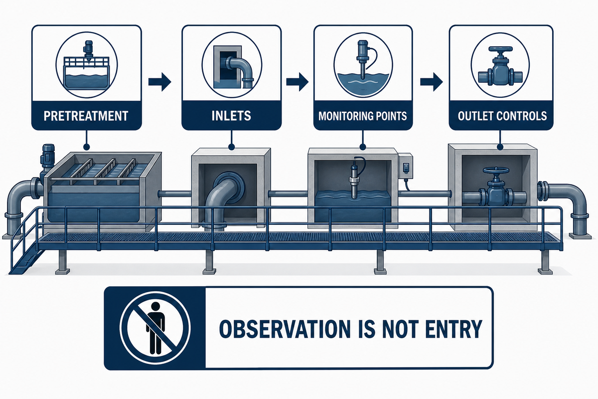
Test for physical monitorability before layout approval. For a porous inlet, inspect the silt trap, identify where the flow path can clog, and decide whether access can enhance maintenance and make it more cost effective. Having a maintenance schedule provides little value if crews can’t access pretreatment, inspect water levels, assess outlet performance, remove sediment, or clean a path without an unsafe entry. As an example, identify which observation would trigger sediment removal and how the maintenance team would reach that component.
EPA guidance outlines responsible parties, schedules, inspection requirements, sediment management, and cleaning of inlets and outlets. Underground guidance identifies inlets, subdrains, monitoring wells, and overflow outlets as inspection points. Convert that into named components, measurable criteria, and ownership. STEP’s underground-system guidance gives the component-level inspection context.
Inspection ports are observation features, not an entry authorization. They don’t establish a safe method for confined entry. If the only way to clean the asset is to provide access that the asset can’t safely provide, then consider that a constraint to the design before construction. As an illustrative access test, ask the maintenance operator to describe how a blocked outlet would be reached and cleared. Record an access failure as a design issue because a written cleaning schedule cannot resolve an unreachable component.
How do you select a system within the whole drainage strategy?
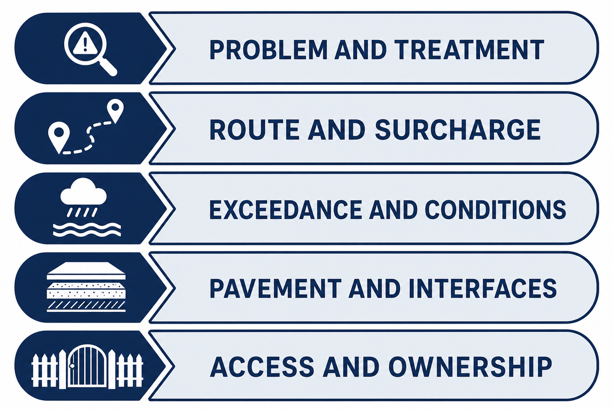
Use ten questions to define the project brief before selecting a system. What problem do we solve? Where is the treatment done? Is this attenuation or infiltration? What happens when there’s surcharge? Where does excess go? What are the controlling conditions? Who accepts the pavement? Where do the interfaces become concealed? What can be measured and cleaned? Who keeps the records and performs maintenance?
For model-specific geometry, declarations and installation documents, please review AQUA’s shallow geocellular sub-base system. For company background and support context, check out About AQUA. Use these resources after the project team has established the performance brief and not as a substitute for it.
Prepare a reviewable design brief
Send the drainage route, footprint, levels, traffic, pavement build-up, groundwater evidence, outlet conditions and access plan. AQUA can then respond against a defined system duty.
Frequently asked questions
Can a shallow geocellular system replace a traditional aggregate sub-base?
Answer
Only when the complete pavement and drainage design supports that role. Formation, traffic, cover, surfacing, restraint, connections and long-term deformation evidence still need verification. The responsible pavement designer should also confirm construction loading and the consequences of local damage. A cell strength figure alone doesn’t approve the installed pavement or justify a volume-for-volume material swap.
How do I choose between infiltration and attenuation?
Answer
Start with ground, seasonal groundwater, contamination and discharge evidence. Infiltration needs verified soil performance, an agreed adjustment basis and suitable separation conditions. Attenuation needs a controlled outlet plus a safe exceedance route when the outlet is restricted or surcharged. Agree the route before selecting geometry because wrapping, connections, pretreatment and maintenance access can all change with that decision.
How much excavation depth is required?
Answer
Add formation preparation, bedding, module depth, cover and the complete surface build-up. Then include falls, connections, construction tolerances and any local thickening required by the pavement design. Check the coordinated utility model and groundwater level against the full profile. A shallow unit doesn’t automatically produce a shallow installed system, particularly where outlet levels control the formation.
Can the system be used under traffic?
Answer
Potentially, subject to a verified pavement design for the actual traffic spectrum and site. Confirm formation strength, cover, repeated and exceptional loads, lateral restraint, settlement criteria and construction sequence. Include construction plant and emergency vehicles where applicable.
How should the system be inspected after installation?
Answer
Follow accessible components from pretreatment through inlets, monitoring points, outlet controls and exceedance routes. Record sediment, blockage, damage, water levels and maintenance actions. Don’t treat a port as permission for entry.
References & Sources
- UK Government: National standards for sustainable drainage systems
- Journal of Civil Engineering, Science and Technology: geocellular system review
- Minnesota Pollution Control Agency: permeable pavement design criteria
- Minnesota Pollution Control Agency: selecting stormwater practices
- US EPA: stormwater maintenance
- US EPA archive: green infrastructure cost and benefit resources
About the author

Grayden Du
Export Director · AQUA RainWater Solutions
Grayden Du is Export Director at AQUA RainWater Solutions. His work spans geocellular detention systems, underground stormwater storage and subsurface water management. Drawing on more than 16 years of hands-on experience across over 30 country markets, he explains technical principles, system choices and practical project requirements.
About AQUA RainWater Solutions
AQUA RainWater Solutions manufactures geocellular stormwater modules, shallow attenuation systems and ground-reinforcement grids, and coordinates the supply of geomembranes, geotextiles and EPDM pond liners. We help match system interfaces and specifications, with batch inspection for moulded products, product documentation and export-delivery support.
![Ground Grid Applications & Ground Reinforcement [Guide]](https://aquarainwater.com/wp-content/uploads/2026/09/ground-grid-applications-ground-reinforcement-blog-featured-768x512.png)