Get in touch with AQUA Company

Ground Grid Applications & Ground Reinforcement: A Practical Field Guide
![Ground Grid Applications & Ground Reinforcement [Guide]](https://aquarainwater.com/wp-content/uploads/2026/09/ground-grid-applications-ground-reinforcement-blog-featured.png)
Updated September 2026 · Educational guide from Aqua Rain Water
Ground Grid Applications & Ground Reinforcement decisions are generally site decisions, not product decisions. Although a grid can confine aggregate, spread a surface load, decrease rutting, and protect permeable grassed surfaces, a grid won’t address every subgrade issue such as rutting, compaction, poor drainage, blocked drains, unsuitable edges, and improper traffic patterns. This guide provides project owners, civil engineers, contractors, landscape teams, and purchasers with a consistent approach to determine the need for a surface reinforcement system and to capture the preparation, the placement, and the post-installation activities.
The short answer
- Identify the problem to be addressed (rutting, aggregate loss, ponding, erosion, vegetation loss).
- Evaluate the site as a vertical build-up of subgrade, separation, base, grid, fill, surface, edges and drainage.
- Choose the application (traffic, water, soil, maintenance, approvals) rather than the product.
- Implement hold points to ensure that subgrade, base, grid placement, fill, edges, and final levels are complete, documented, and assigned.
- Diagnose symptoms by layer prior to removing the grid or adding material.
- A complete project brief is required for specification and quotation. This article doesn’t replace site-specific engineering.
The commercial ground grid applications solution page is the location to review products and start a discussion. This document has a different role. It explains how to examine the site and consider the options, check the work, and provide a functioning system without using a supplier’s catalog description as a design aid.
For each measurable item include the following unit values: area in square meters, level or cover in millimeters or meters, pressure in kilo Pascals, response to traffic in liters per second (if relevant), temperature in °Celsius, sampling in percent, and time of inspection in hours or days. These units are reporting values and not design values. The project team should replace the reporting values with surveyed or approved values.
First separate surface reinforcement from electrical grounding
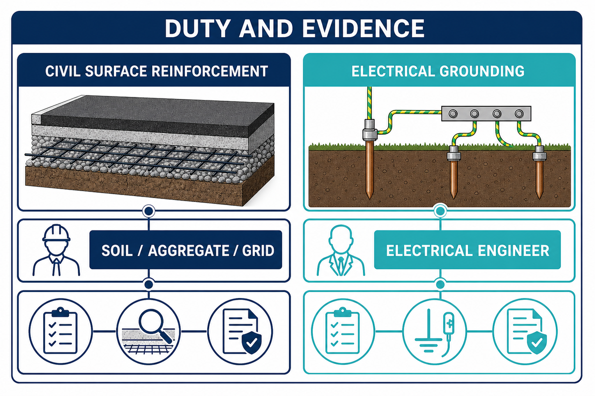
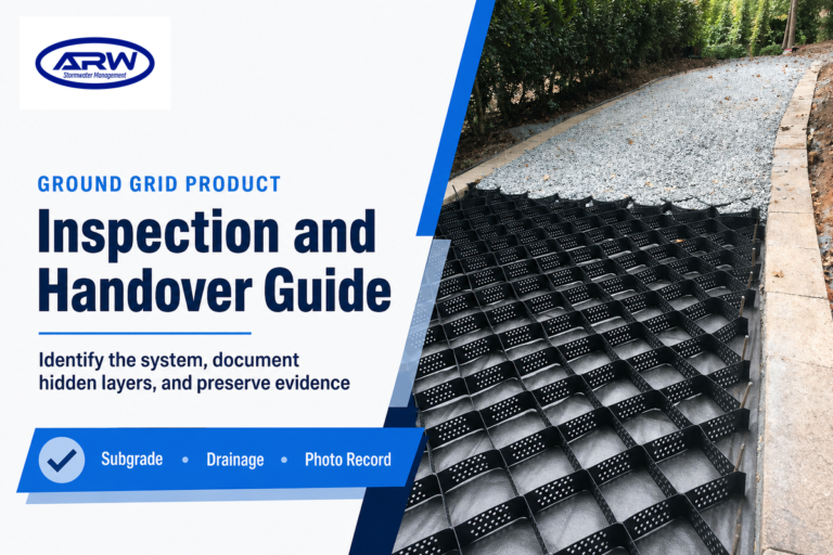
In civil and landscape works, “ground grid” refers to a layer of geosynthetic or cellular material used in combination with soil and aggregate. It can constrain fill, minimize lateral spread, improve load distribution or protect a surface from repeated traffic. Electrical grounding grids are a different branch of engineering dealing with conductors, fault current, bonding, earthing and electrical safety. Civil ground-reinforcement writing shouldn’t be construed as providing electrical design advice.
This distinction is important for search, procurement, and risk control. Include in the brief the requested duty: ‘surface ground reinforcement for gravel, grass, access, or erosion control’. If an electrical engineer requests an earthing grid, then issue a scope, drawing, calculation, and safety review. Don’t confuse a similar phrase and attract the wrong specialist, product family, or a test requirement in the package.
The civil definition is also conditional. One grid is one of many layers in a build up, and won’t provide a pavement, drainage system, retained structure, or a traffic design. The incorrect question is “can a grid carry this?” The correct question is “which layer is responsible for each duty and what evidence supports that the complete build up is adequate?” See ISO/TR 18228-5:2025 for general geosynthetic stabilization guidance; local design and construction requirements still control.
Field rule: Treat the grid as one layer in a complete build-up. Confirm the failure, base, water path, edge condition, and inspection evidence before discussing a product.
Start with the failure you need to prevent
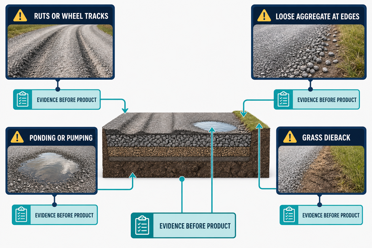
When considering a grid selection, record the failure you see or anticipate. The gravel driveway may scour due to rutting. The service lane may haze after fines suspension. The grass parking space may lose its soil structure before the grass grows. The slope may wash out at the base. The pedestrian path may spread aggregate into a drain. All of these failures can be attributed to a different combination of layers, materials, and controls.
| Observed or planned problem | First questions | Evidence to collect |
|---|---|---|
| Ruts or wheel tracks | Where is the weak layer? How often do turning loads occur? | Traffic map, levels, soil observations, photographs after rain |
| Loose aggregate at edges | Is the fill confined? Is the edge or transition shedding water? | Edge detail, crossfall, drain path, maintenance history |
| Ponding or pumping | Is water trapped above, below, or beside the reinforced layer? | Rain observations, infiltration or drainage notes, low points |
| Grass dieback | Was the root zone prepared and protected during establishment? | Soil profile, seed or turf record, irrigation, traffic timing |
| Loose or migrating aggregate | Is the fill grading suitable and is the edge restraint intact? | Fill grading, restraint detail, turning and sweeping history |
| Exposed grid cells | Was cover lost through traffic, erosion, or incomplete filling? | Surface photos, cover observations, runoff path |
| Edge unraveling | Is the transition restrained and tied into the adjacent surface? | Edge detail, movement photos, kerb or tie-in condition |
| Pumping or fines loss | Is water carrying fines through a weak layer or open interface? | Wet-weather photos, fines trail, inlet and outlet condition |
| Trip or level change | Has fill loss or settlement created a raised transition? | Level readings, transition photos, pedestrian route record |
Using this method of describing failures first may also avoid a very expensive mistake. If the real problem is an unsealed slope or a soft formation, the installation of a stronger-looking grid may shift the problem without addressing the cause. Be sure to describe the failure and the suspected layer and the field check that will either prove or disprove your hypothesis. The ISO/TR 18228-5:2025 guidance provides a general stabilization reference, not a project-specific approval.
The wording used isn’t a product claim: “ground reinforcement grid” for a civil layer, “ground grid for gravel” for a confined aggregate surface, and “ground grid for grass” for a permeable and/or vegetative layer. Each ground grid inspection checklist and each ground grid sub-base note, rutting repair record, and ground reinforcement inspection record should describe the site, layer, the material, the date, the owner, and the evidence. These terms describe the work scope; they don’t prescribe the design. The Federal Highway Administration gravel-road guide is a useful authority for the drainage, layer, and maintenance context.
Use the 6-Layer Ground-Reinforcement Map
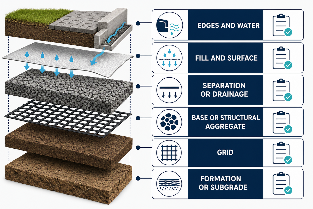
The Ground-Reinforcement Layer Map is a simple planning tool. Visualize a drawing of the surface as a stack; one duty can be assigned to each layer. The Ground-Reinforcement Layer Map isn’t a standard section and doesn’t set universal thicknesses; it serves to show missing interfaces before the construction process begins.
- Formation or Subgrade: the soil or prepared ground that receives the work. Note the strength, moisture, contamination, soft spots, and proof rolling.
- Separation or Drainage Layer: a geotextile, drainage path, or other approved interfaces as needed. Describe what it separates or conveys.
- Base or Structural Aggregate: the layer that provides stiffness and load distribution. Indicate the source, grading, moisture, and level of compaction as required by the designer.
- Grid: the reinforcement or confinement layer. Describe orientation, overlaps or connections, anchoring, and any limitations as allowed in the approved detail.
- Fill and surface: aggregate, soil, turf, pavers, or some other finish. Describe how cells are filled and how the surface is trimmed and how traffic is kept off until released.
- Edges and water: kerbs, transitions, swales, drains, outlets, and paths for overflow and excess water. A lot of “grid failures” begin at this interface.
| Layer type | Primary duty | Record before covering |
|---|---|---|
| 1. Formation | Receive the build-up | Soft spots, moisture, levels, utilities |
| 2. Separation | Keep unlike materials or water paths distinct | Material, overlap, drainage direction |
| 3. Base | Provide level and distribution | Source, grading, moisture, compaction method |
| 4. Grid | Confine or reinforce the nominated layer | Orientation, connections, anchors, damage check |
| 5. Fill | Create the working surface | Fill type, placement sequence, final level |
| 6. Edge | Hold the boundary and transition | Kerb, tie-in, slope, restraint detail |
| 7. Water | Move or shed water safely | Crossfall, inlet, outlet, overflow path |
| 8. Traffic | Control when and how the surface is loaded | Vehicle class, turning, release condition |
| 9. Maintenance | Keep the duty working after handover | Trigger, access, owner, response record |
A measurement register might carry 50 mm of observed settlement, 100 mm of edge movement, a 1 m transition, a 2 m access clearance, 5 kPa of recorded pressure, 10 L/s of an approved flow note, 20 °C of a test condition, a 24 hr response target, or a 2% factory sample. The values mentioned provide a traceable field and context in the given examples. The values aren’t standard construction or design values.
An approving register can recognize an 80 mm repair, a 150 mm level check, a 300 mm temporary cover note, a 5 m drainage reach, a 10 kPa observation, a 30 min inspection window, a 48 hr close-out target, or a 300 m² work area. Preserving a unit with source and owner can differentiate a field note from a generic specification.
Include the governing temperature as 12 °C, a nominated construction action as 25 kN, a 72 hr weather hold, or a 500 m² inspection zone. It isn’t a hidden recommendation but rather a consistent naming convention.
As examples to fill a clean evidence row, one team could label a 1 year review, 2 days of restricted access, 3 hr of curing or weather hold, 4 mm of measured level difference, 5 m of edge length, 6% of an approved sample, 7 °C of a test condition, 8 m² of repair, 9 kg of retained material, or 10 months until the next planned inspection. Substitute every example with the project’s approved value before construction.
The map has found a coordination gap if a drawing shows a grid but not its base, edge, water, or maintenance assumptions. ISO/TR 18228-5:2025 generally provides guidance for geosynthetic stabilization, but the project team still has to fulfill the governing local design and construction requirements.
Gravel driveways and access lanes
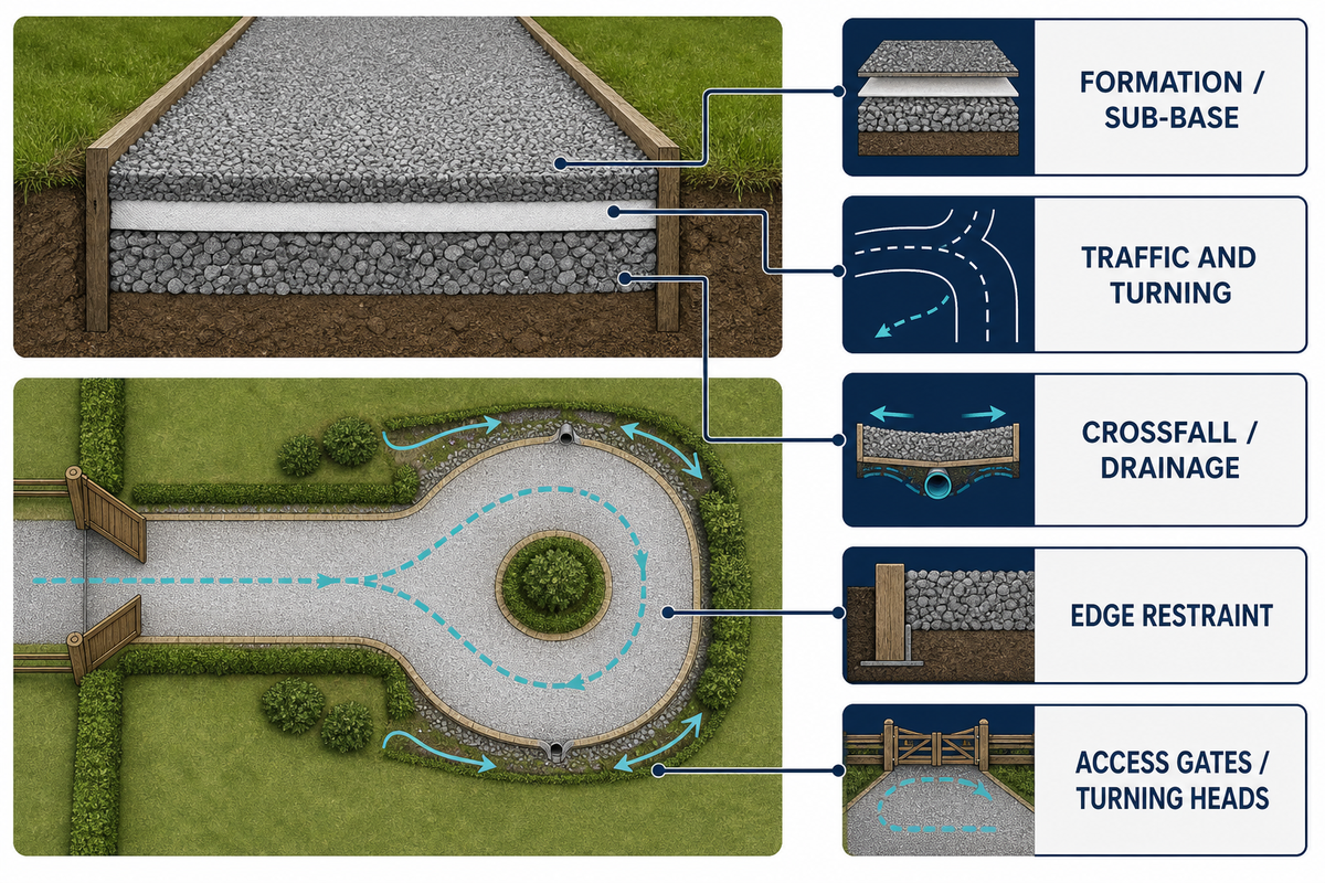
Gravel driveways are often easier to maintain and cheaper due to the natural tendency of gravel to settle. While each design requires different features and components, many driveways do well without a grid system. Sub-base, sub-grade, design traffic, accessibility for ease of driveway maintenance, turning movements, crossfall, drainage, and edge restraint must all be considered. One light footpath used for infrequent access and perhaps a delivery lane and fire route shouldn’t be designed as a single roadway.
Preparing the formation involves addressing the necessary line and level, positioning, and if necessary placing a separation layer. It involves the removal of undesirable sub-base, management of the available water, and compaction of the base to the specified standard. Gravel base grids won’t provide a long term solution over wells, pumped zones, or saturated base grids. Refer to the Federal Highway Administration publication for good construction practices for drainage and layers. It isn’t an endorsement of a product load certificate.
Prior to filling the voids within the grid framework, consider the drainage along the length of the grid, and whether the gravel ties into an adjacent paved surface. Consider whether there’s adequate edge restraint to prevent loss of the fines through potential water discharge. Consider where the panels are placed along the length of the grid at access gates and turning heads to ensure adequate stopping sight distance and steering clearance.
Don’t assume quotations used on a competitor’s project apply to your project. Those statements are specific to their product and the tests performed on those grids. Request details of the test scope, the method of installation, and the design and installation constraints. Compare the drainage and layer assumptions with the Federal Highway Administration reference before accepting a project-specific claim.
Grass, event, and overflow parking areas
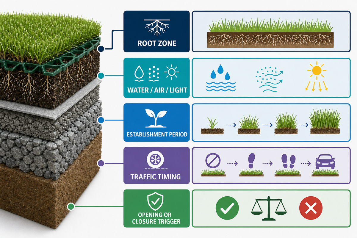
Grass reinforcement combines both civil and horticultural practices. The grid may alleviate tyre shear damage or help retain a soil or aggregate infill. Grass also needs a root zone, water, air, light, and both a period to establish and a plan to maintain it. Traffic timing is critical to the success or failure of a surface. Healthy surfaces can fail if a crowd or vehicle load arrives before the roots have had a chance to grow. Use the ISO/TR 18228-5:2025 guidance as a general geosynthetic reference, not as a grass-establishment specification.
Use the same Layer Map and add a living-surface overlay. Record if the area will be used for occasional overflow parking, regular parking, emergency access, a pedestrian event, or a shared-use verge. Mark the location of entry and exit of water, a repairable edge, and how the owner will seal the area after heavy rain. Grass reinforcement must be judged by the root zone and maintenance plan, and not just by the grid, in this case.
For a grassed event area, a release note may say “Open to vehicles after establishment inspection; close after rainfall trigger; expose cells before the next event.” The trigger and timing should be decided by the project team. The supplier can explain product handling, policies, and procedures, but should not set the owner’s traffic policy, define local growing conditions, or direct project-specific growing practices.
Paths, slopes, and erosion-prone transitions
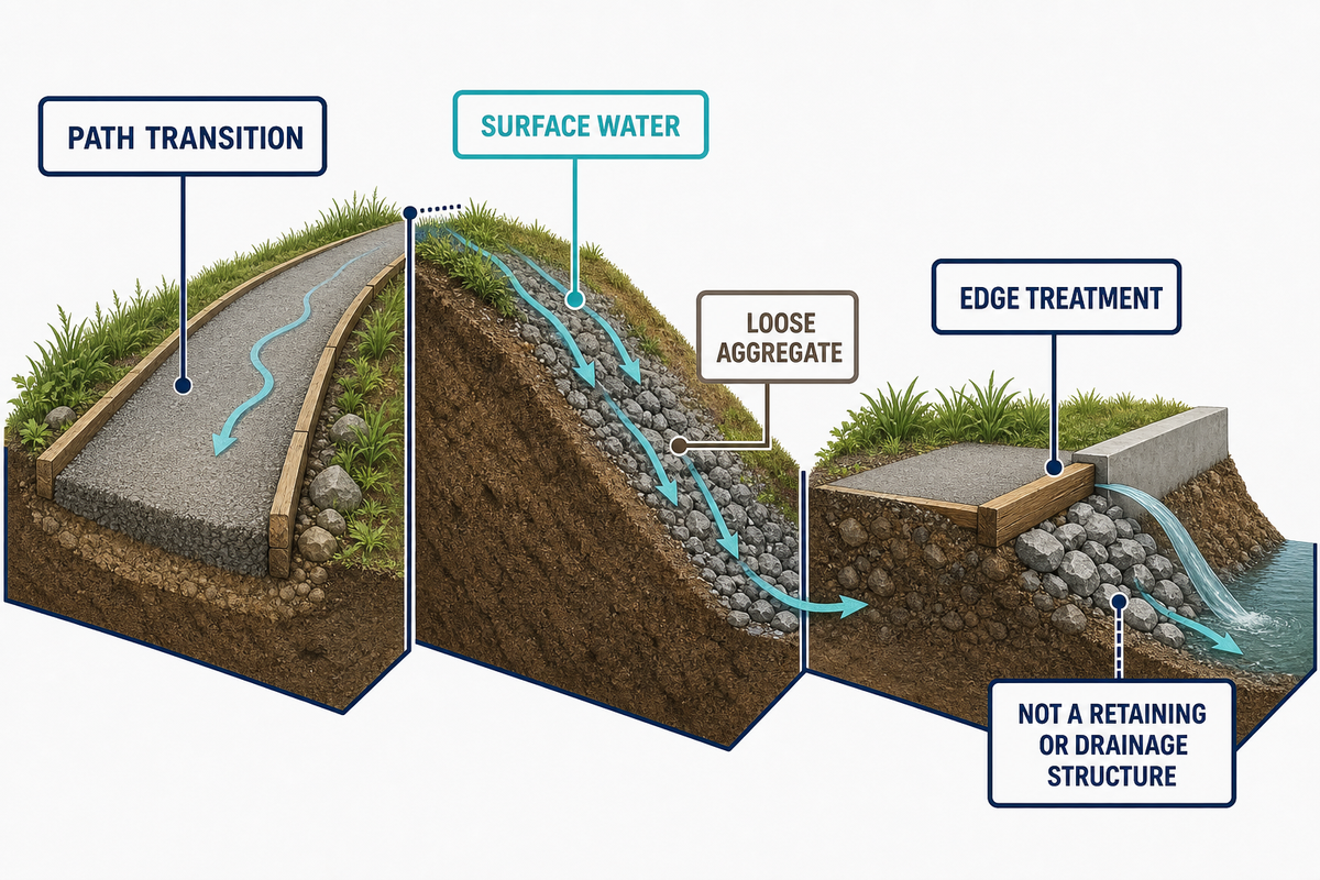
Transitions are a common point of failure for paths and slopes. Runoff from one end of a path may create extra flow and erosion. Slopes may create extra flow due to concentrated runoff in a reinforced area. An interrupted load path may be created by a barrier such as a kerb, drain, culvert, or a retaining edge. Draw and examine these interfaces on a plan and section after the first major rainfall. The Federal Highway Administration reference reinforces the need to keep drainage and layer decisions visible.
Be sure to check the slope for temporary anchoring, the sequence of placement that doesn’t cause loose aggregate to move, and access for fill. The installer should document the actual sequence, weather, deviations, and edge treatment.
Marketing language isn’t a substitute for a retaining wall, a lined channel, a check dam, or a permitted drainage outlet. If the load applied to the system is exceeded by either earth or water pressure, then the design must be redone by a qualified professional.
A field installation sequence that can be inspected
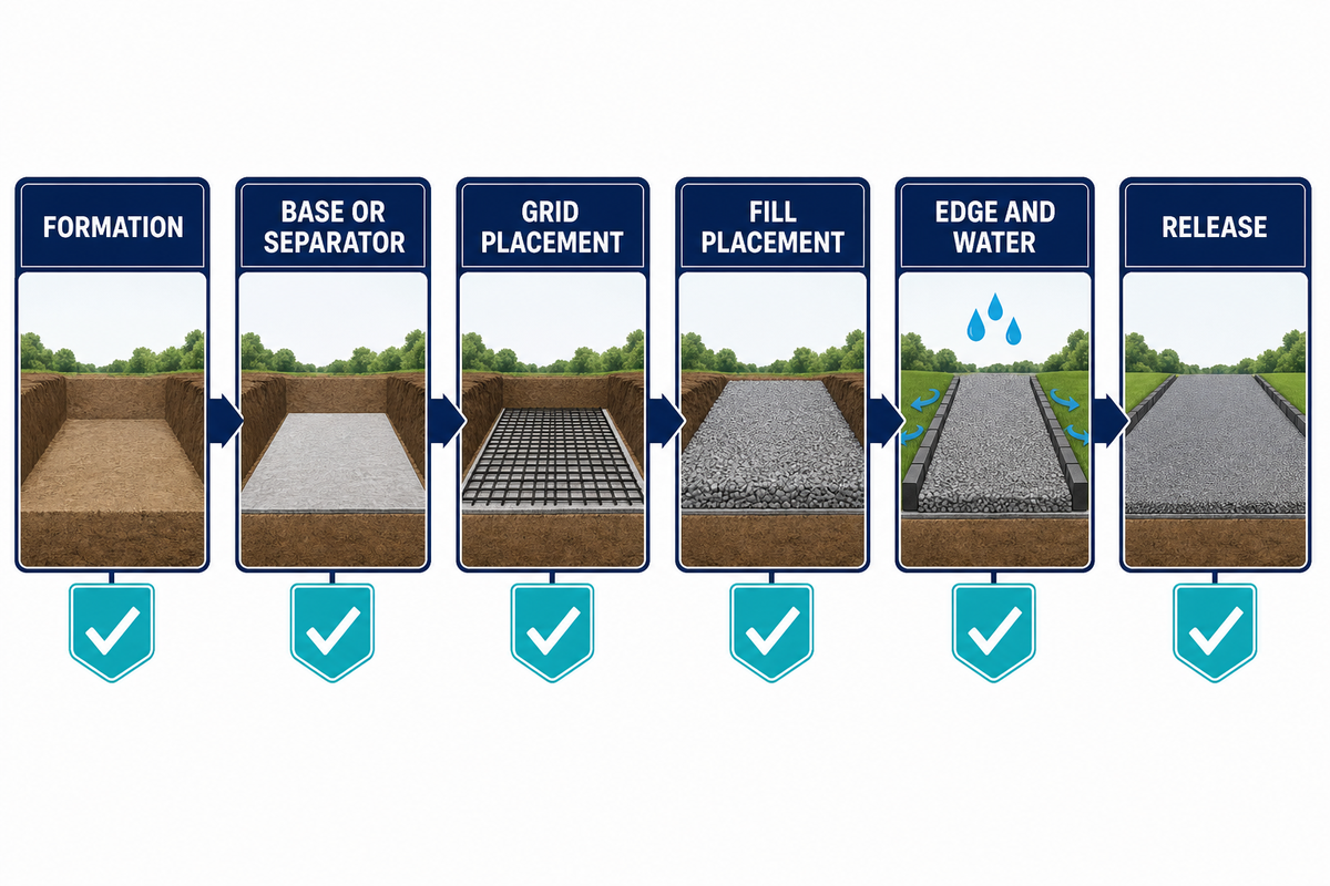
Separate the work into hold points. Each hold point needs an acceptance question, a record, and an assigned owner. Managing this way gives a reliable record without claiming a blog checklist is a construction standard.
6-Point Hold-Point Handover Sheet
- HP-01 Formation: Limits, soft spots, moisture, levels, utilities, and drainage observed and recorded before cover.
- HP-02 Base or separator: material, line, level, overlap or joint detail, and evidence of compaction checked.
- HP-03 Grid placement: photos of each panel, panel connections, anchoring, damage, and boundary dimensions.
- HP-04 Fill placement: record of type of fill, sequence of fill, spreading method, coverage of each cell, surface level, and restriction of movement across the surface.
- HP-05 Edge and water: checks of kerbs, transitions, inlets, outlets, crossfall, and path of overflow completed and signed.
- HP-06 Release: area opened, as-built changes, maintenance trigger, assigned owner, and next inspection date accepted.
Include a photograph that shows a fixed reference, not only a close-up. Please include the location or chainage. Also, please include the date the photograph was taken, the weather at that time, and the person taking the photograph. If a check isn’t applicable, please state the reason. Don’t leave a blank space that could be assumed to indicate an undone inspection. Use the Federal Highway Administration inspection reference as a context check, not as a substitute for the approved method.
Inspection, acceptance, and maintenance records
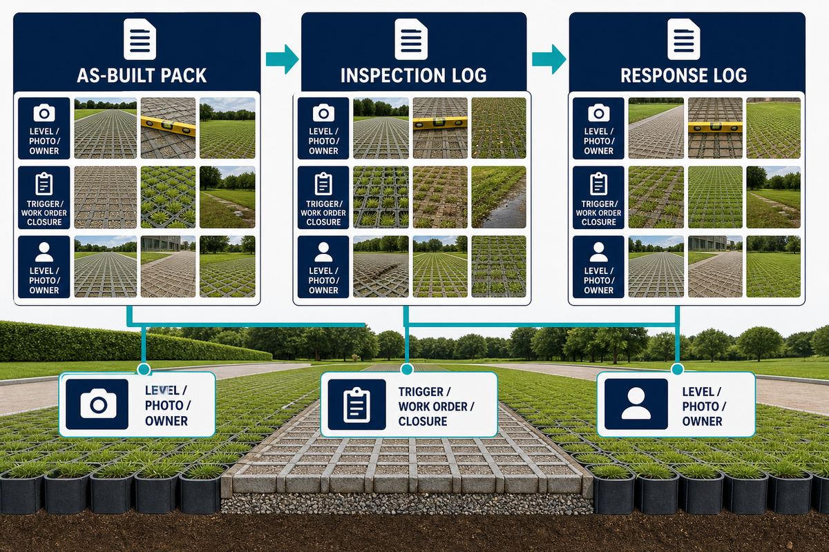
Acceptance should include level measurements alongside visual checks, drainage paths, photos, and names of owners. Even with a smooth surface, drains may still be blocked or installed downstream of the fill. Unrecorded deviations may leave a local repair poorly connected to the surrounding work. Record the scale and location of the observation.
Create three linked records: an as-built pack, an inspection log, and a response log. The as-built pack records the completed section and captures boundary, level, material, photo, change, and snapshot information. The inspection log captures the conditions, measurement, photograph, weather/traffic, and trigger. The response log captures closure reviewer, work order, repair assessment, and decision. The Federal Highway Administration maintenance reference provides a useful public checklist context.
The supplier may offer product documentation, batch inspection data, export packing, loading supervision, remote factory inspection, and agreed test videos. AQUA Rain Water’s factory record states an operation of core moulded-products that began in 2009 with around 15 years of experience in exporting, 30 injection molding machines, a two-shift system, and around 2% inspection of moulded product batches for dimension, color, appearance, and compression. These are first-party, bounded process data for the relevant moulded range. They aren’t third party certifications, don’t apply automatically to procured geotextiles, geomembranes or EPDM batches, and don’t make Aqua the installation contractor.
Maintenance and failure diagnosis
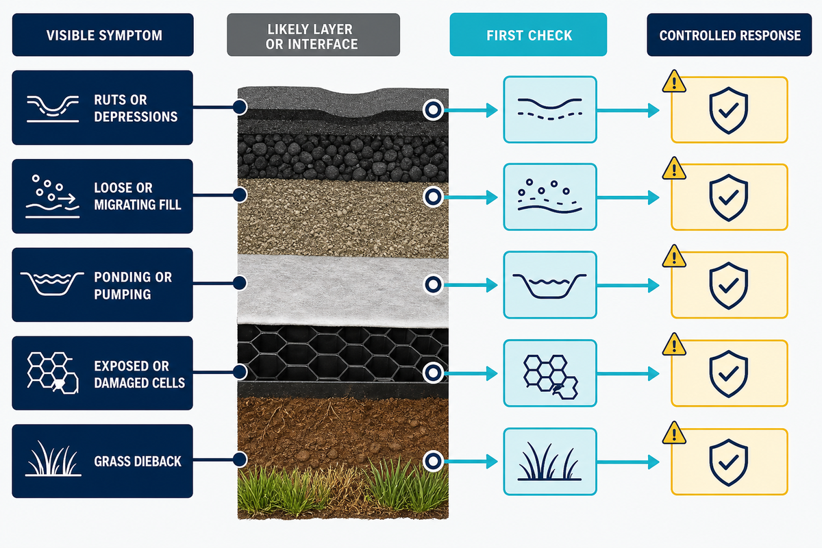
It’s more effective to perform maintenance after the first check follows the symptom to its likely layer or interface. A ground grid maintenance record should link each trigger to the responsible owner, while a ground grid rutting repair record should identify the failed layer, approved corrective detail, photographs, and reinspection result. The same surface can exhibit different causes after a wet season, a delivery period, or a change in adjacent drainage. To avoid the team immediately blaming the product, use a diagnosis table.
| Rutting-to-Root-Cause Table | First check | Possible response |
|---|---|---|
| Ruts or depressions | Subgrade, base thickness, water, turning loads, and compaction record | Isolate traffic, investigate the layer, then repair to the approved detail |
| Loose or migrating fill | Cell fill, edge restraint, slope, and sweeping or ploughing activity | Replace fill, correct edge or method, and document the boundary |
| Ponding or pumping | Low point, blocked drain, impermeable interface, and groundwater | Clear or redesign the water path; do not assume extra grid will drain it |
| Exposed or damaged cells | Construction traffic, scour, fill loss, and edge movement | Restrict traffic and repair with a recorded method and inspection |
| Grass dieback | Root-zone depth, moisture, compaction, shade, and traffic timing | Restore the growing condition and revise the traffic or irrigation plan |
The triage table has its limits. Take photos of the area before servicing and compare it to the as-built documentation. Involve the designer if you determine the cause of the failure to be in the structural, hydraulic or geotechnical systems, or within a safety-critical part of the system. Simply entering “filled rut” into the maintenance log leaves out the information needed to prevent the failure from recurring. Use the Federal Highway Administration maintenance guidance as a general reference while retaining the project method and approvals.
What to put in a supplier or project brief
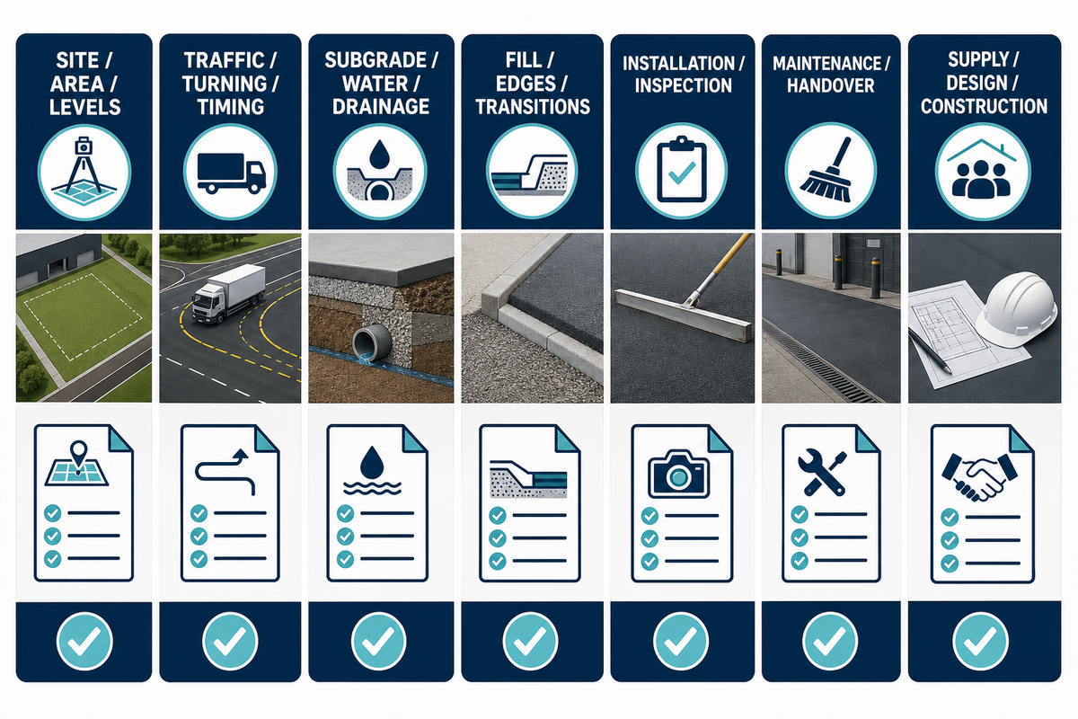
A useful brief guides suppliers on what questions to answer and allows project teams to compare answers. Search labels such as “geocell ground grid for driveway”, “ground grid for pavers”, and “ground grid for walkway” describe different application questions, not a universal design. The ISO/TR 18228-5:2025 reference can frame the geosynthetic stabilization context, but it does not approve a project brief.
- site location, area, plan, levels, slope, boundaries, utilities, and surface intended;
- type, frequency and timing of traffic, turns, emergency access, event use, and the date when traffic may start;
- observations of subgrade, notes on groundwater or wet-weather conditions, assumptions on base and separation, and drainage paths;
- fill or surface material, edge conditions, transitions, slopes, and any local authority requirements;
- installation sequence, inspection hold points, photos, test records, deviations and owners;
- maintenance triggers, access limitations, repair obligations, and relevant documents to be handed over; and
- the precise boundary of product supply, technical support, installation construction, design approval and operation.
Keep the Commercial Request Separate from the Educational Diagnosis
The solution page enables a confirmed duty to be converted into a product configuration and quote request. The brief must include the site evidence to support and justify that request. No request should be made for the ‘best grid’ as the decision for that depends on layers, water, traffic, edges and future maintenance.
Frequently asked questions
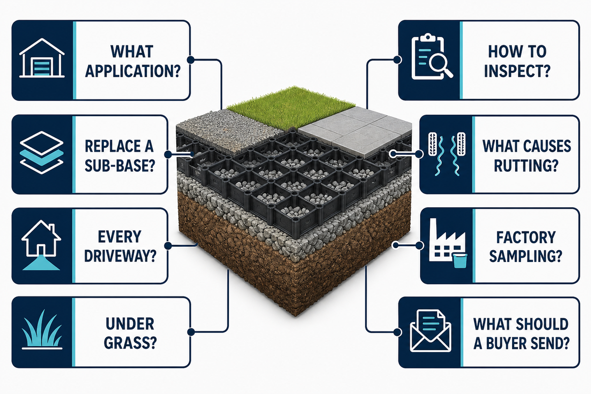
What are ground grid applications?
Read the practical answer
Ground grid applications are civil or landscape uses of a grid or cellular reinforcement layer with soil, aggregate, or a vegetated surface. Common examples include gravel drives, access lanes, paths, slopes, erosion-prone transitions, event or overflow parking, and grassed surfaces. The grid is normally one layer in a build-up, so the site still needs an appropriate formation, base, water path, edge treatment, and maintenance plan. A practical decision starts with the failure signature and the intended traffic, not a catalogue image. Ask what happens at a wet edge, a turning head, a blocked drain, an unfinished grass root zone, or a change in maintenance ownership. Then record which layer handles that condition, which person inspects it, and what photograph, level, test, or approval closes the item. This makes “ground grid applications” a controlled project topic rather than a promise that one surface product can solve every ground problem.
Do ground grids replace a sub-base?
Read the practical answer
Not as a universal rule. One grid can reinforce or confine a layer, but it doesn’t automatically turn weak, wet, contaminated, or poorly drained ground into a suitable formation. The project designer should assess the subgrade, the required base, separation or drainage layer, traffic, water, and edge conditions. The complete Layer Map is more reliable than assuming the product name answers the sub-base question.
Are gravel grids suitable for every driveway?
Read the practical answer
No. Suitability depends on the formation, aggregate, drainage, traffic pattern, turning, slope, edge restraint, and maintenance access. Residential footpaths, delivery entrances, and fire routes have different duties. Before choosing a grid, document the failure you need to prevent and the evidence that will show the surface is ready for traffic. Product-specific capacity statements must be matched to the actual test and installation boundary.
Can a ground grid be used under grass?
Read the practical answer
It can be considered for some grassed or permeable surface applications, but grass performance depends on the root zone, moisture, drainage, light, establishment period, traffic timing, and maintenance. Grid systems can’t compensate for compacted soil, persistent ponding, or traffic that arrives before establishment. Define an opening or closure trigger and record who will inspect the surface after heavy rain or an event.
How should a ground-grid installation be inspected?
Read the practical answer
Use hold points for formation, base or separator, grid placement, fill, edges and water, and final release. At each point record the acceptance question, material or condition, level or location, photograph, deviation, and named owner. Keep the as-built, inspection, and response records together. This is an inspection framework for coordination; the approved construction method and local requirements remain controlling.
What causes rutting after a grid is installed?
Read the practical answer
Rutting can come from the subgrade, base, water, compaction, fill loss, turning loads, construction sequence, or an edge that lets material escape. Start with the Rutting-to-Root-Cause Table: photograph the symptom, compare it with the as-built and weather record, inspect the layers and drainage, then choose a repair. Adding more surface material before identifying the weak layer may only hide the cause temporarily.
Does factory sampling prove site performance?
Read the practical answer
No. Factory sampling, product tests, and certificates have a defined product, method, date, and scope. They don’t replace the project designer’s checks for soil, base, cover, water, traffic, installation, and local approval. Aqua’s supplied record describes approximately 2% sampling for dimensions, colour, appearance, and compression for relevant moulded-product batches; that bounded process fact isn’t third-party certification or a site acceptance result.
What should a buyer send before requesting a configuration?
Read the practical answer
Send the area and plan, surface duty, traffic and turning, subgrade and water observations, base or separator assumptions, fill, slope and edge conditions, installation sequence, inspection evidence, maintenance triggers, delivery timing, and the exact support boundary. State what the supplier is expected to provide and what remains with the designer, installer, owner, or authority. This complete brief reduces clarification rounds and prevents a generic product answer from being mistaken for design approval.
Need to turn a site brief into a product conversation?
Present your plan, traffic duty, layers, drainage, edge details, photos, and handover requirements. Aqua Rain Water can assess the product side and supporting documents, while project design, approval, and construction remain with the appointed project team.
References and sources
The references below support the planning and inspection principles in this guide. Manufacturer and supplier pages are used for application context, not as independent certification. Always confirm the current edition and jurisdiction-specific requirements with the project authority.
- Federal Highway Administration, Gravel Roads: Maintenance and Design Manual layers, drainage, inspection, and maintenance.
- ISO/TR 18228-5:2025, general guidance on the geosynthetic stabilization of granular layers.
- Tensar International, What is geogrid and how does it work?: definition and reinforcement context of a civil geogrid.
- Strata Geosystems, geogrid installation guidelines, subgrade, placement of aggregate and compaction, and drainage.
- American Society of Civil Engineers, construction inspection of geosynthetic reinforced systems: inspection and documentation principles.
- California Department of Transportation, Construction Manual Section 4-96: Geosynthetics: placement, line-and-grade, damage, drainage, and pre-cover inspection checks.
- Ecodeck, ground reinforced grids, competitor applications for grass and permeable surfaces.
Aqua factory figures in this article are based on the owner-confirmed factory record for this project and are limited by the product, material, order-mix, testing, and season qualifiers in that record.
About the author

Grayden Du
Export Director · AQUA RainWater Solutions
Grayden Du is Export Director at AQUA RainWater Solutions. His work spans geocellular detention systems, underground stormwater storage and subsurface water management. Drawing on more than 16 years of hands-on experience across over 30 country markets, he explains technical principles, system choices and practical project requirements.
About AQUA RainWater Solutions
AQUA RainWater Solutions manufactures geocellular stormwater modules, shallow attenuation systems and ground-reinforcement grids. We support product configuration, batch inspection, export packing, loading supervision and product-related documentation.