Get in touch with AQUA Company

![Aquavoid System Shallow Surface Drainage [Guide]](https://aquarainwater.com/wp-content/uploads/2026/10/aquavoid-system-shallow-surface-drainage-blog-featured.png)
Updated October 2026
Quick specifications: keep the products separate
- AquaVoid: Naylor’s modular underground stormwater storage family.
- AQUA ARW-SA: a separate shallow module range with a published 1000 × 500 mm footprint.
- ARW-SA heights: 85, 150, 200 and 250 mm; published void ratio 95%.
- Selection basis: receiving route, hydraulic levels, complete build-up, structural assessment and accessible maintenance.
Aquavoid system shallow surface drainage refers to how AquaVoid, by Naylor, stores stormwater below ground, while other surface measures manage runoff to that storage. A tank can’t collect water that the surface layout never delivers to it. The AQUA shallow attenuation tank range is a different product family.
Aquavoid system shallow surface drainage combines surface runoff management with underground storage. Confirm the exact Naylor product, receiving route and complete installed design; a module’s height or void ratio alone does not establish a working drainage scheme.
Key points
- A 150 mm module doesn’t mean a 150 mm excavation.
- Attenuation and infiltration can work together where site conditions and local requirements allow.
- Short-term compression results don’t establish long-term installed load capacity.
- Specify a physical sediment-removal route before committing to modules that can’t be reopened.
What AquaVoid does and what surface drainage does
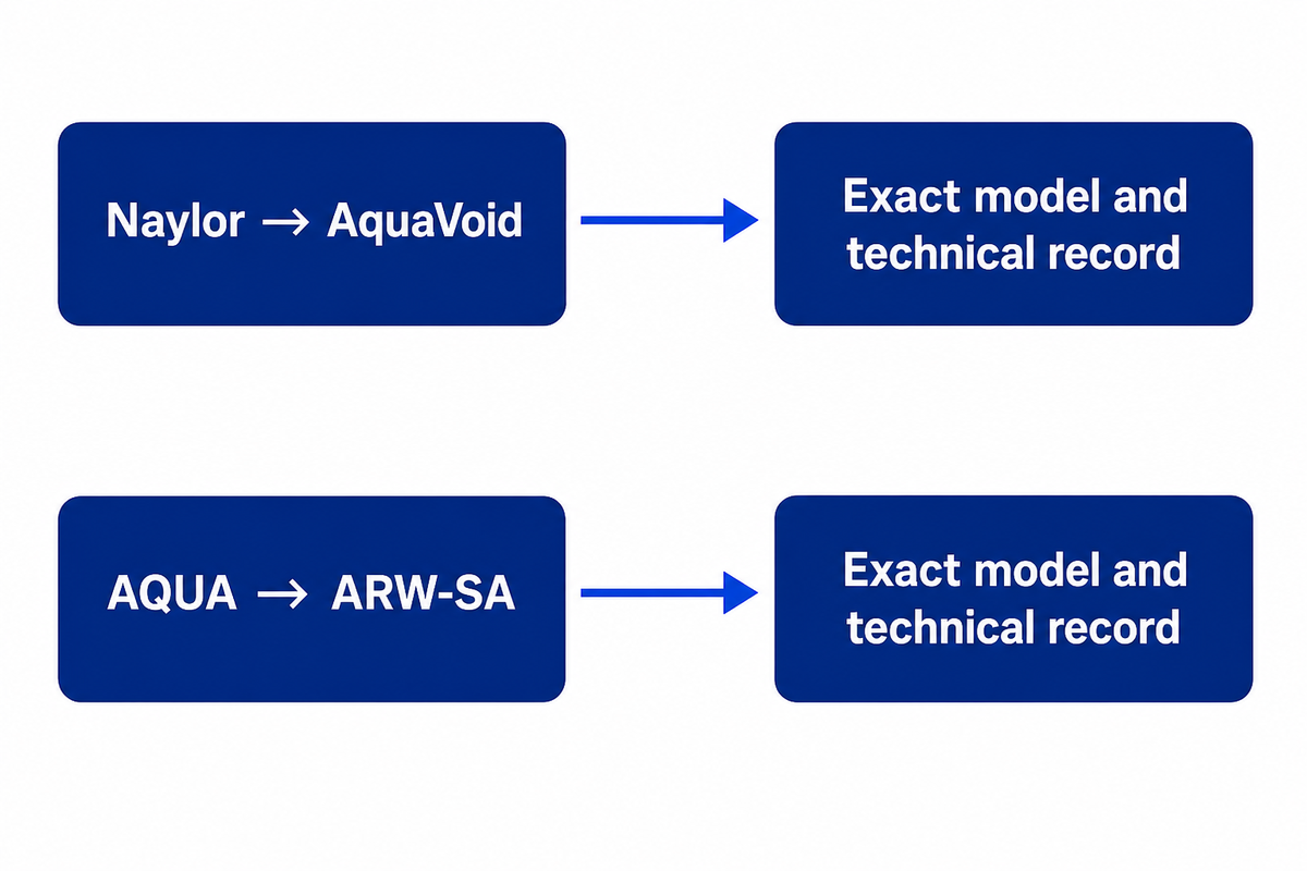
AquaVoid provides water storage below ground as part of a larger drainage system. In surface drainage, management of water at the ground surface is achieved through grading, inlets, channels and vegetated features. Some surface features also store, infiltrate or treat runoff. Product selection starts with matching the named module to its current technical record.
The AquaVoid modular attenuation range includes named variants such as AquaVoid Home, and each variant should be specified on its own sheet. Naylor’s present web page on AquaVoid covers attenuation and infiltration. Its general overview states 96% void space, while the specific AquaVoid table lists 95.5%, a 1.2 × 0.6 × 0.3 m crate and a separate 0.02 m base. The designers should provide the same model, revision and value in the design schedule.
| Published item | What to match | What it does not establish |
|---|---|---|
| Overview: 96% void | Product family and exact variant | The ratio for every crate or generation |
| Specific table: 95.5% void | Named crate and dated specification | AQUA ARW-SA performance |
| 300 mm crate; 20 mm separate base | Complete module assembly | Finished-surface excavation depth |
| Published compression and cover data | Test basis and approved installed arrangement | Automatic approval for another site or supplier |
The CIRIA/Susdrain geocellular component guidance states that, in general, geocellular systems have very limited inherent water treatment and monitoring. A modular attenuation system needs interfaces beyond the crates to provide useful water storage. Keep drainage crate arrangements tied to the named supplier rather than assuming common dimensions imply compatibility.
For the buyer comparing Naylor Drainage information to AQUA literature, the meaningful question is whether each offer has its own matching assembly, capacity and installation evidence. A familiar product name is no substitute for missing information. Request clarification when a quotation combines an overview ratio with an unmatched drawing.
AquaVoid’s published 300 mm crate and 20 mm separate base describe product geometry, while the table’s 95.5% void value concerns that named unit. Keeping those entries together prevents a family-level 96% statement from silently replacing the selected model’s storage input; neither percentage confirms site approval. For AQUA’s application overview, see the shallow-platform applications and distributor overview; this technical guide focuses on product identity, surface-to-storage interfaces and project evidence.
Trace the surface drainage system before selecting underground storage
Effective surface water management uses a surface drainage system to intercept runoff intended for the underground tank, and preserve the planned route for excess water. Trace the ground slope, each collection point and its connection before increasing storage volume. Water standing above a mostly unfilled tank is a reason to investigate the upstream path.
Dry-Tank Ponding Diagnostic
The Dry-Tank Ponding Diagnostic traces collection points, connections and levels, when surface ponding occurs and buried storage remains largely empty.
- Observe the surface. Record where water stands and whether the intended inlet receives runoff.
- Inspect accessible collection points. Check grates and sediment traps before changing tank size.
- Check the connecting route. Compare pipe grades, invert levels and any accessible obstruction with the approved drawing.
- Check storage and outfall levels. Establish where water enters, accumulates and discharges; include downstream backwater.
- Escalate the finding. Ask the designer to review hydraulic capacity and exceedance routing where the observed path differs from the scheme.
The Philadelphia Water Department’s subsurface infiltration manual separates pretreatment, inlet controls, storage, outlet controls and access. This breakdown is useful in tracing water movement; Philadelphia’s local numerical criteria remain local. A dry tank alone doesn’t identify which interface is wrong.
Consider a facilities operator who encounters standing water next to a paved entrance after rainfall, but an accessible inspection point shows little water in the storage zone. Making an order for additional crates leaves the first question unanswered: did the runoff make it to the tank? The operator takes a picture of the ponding edge, notes which surface drains are receiving flow, and checks accessible sediment traps against the maintenance plan.
A designer then checks the collection and connection levels against the as-built record rather than taking the inspection point as proof that the tank is completely empty. Blockages, inlets above the ponding area, and outfalls of different conditions would warrant different corrective actions. The observations limit the study; they don’t give the go-ahead to excavate or increase hydraulic capacity.
What is the difference between surface and subsurface drainage?
Surface drainage controls runoff on ground surface; subsurface drainage systems operate below ground, where their purpose can vary. Buried storm water storage is different from drains designed to remove water from the soil profile or lower the water table. Specify the unwanted water’s source and destination before combining surface and subsurface components.
The types of surface drainage systems appropriate for a site can include channels, point inlets and shallow, vegetated conveyance. Shallow surface drains intercept excess surface water at soil surface. The steepness of the slope and velocity of water affect collection and erosion checks. Appropriately spaced inlets come from that design, not from a tank brochure. A grassed waterway can also provide treatment or temporary storage, and shouldn’t be viewed strictly as a box fed by a pipe.
Surface drainage solutions should be selected only after shallow depressions and water collection have been mapped out. Guiding water away from an entrance means there’s a continuous route to an accepted destination. Effective surface collection area is a design input, not a tank dimension.
To install a surface drainage system, the designer has to link the intended collection points to the receiving route. Proper drainage for a paved area means resolution of those interfaces rather than relying on a crate label. Don’t guarantee to prevent surface ponding based on a tank’s capacity alone.
A surface scheme can remove excess water only through the path provided for it. The designer must distinguish surface and subsurface water sources before treating a buried stormwater module as the solution. Adequate drainage also needs an exceedance route when inflow exceeds the designed capacity.
Good drainage planning links observed water runoff to the layout that can control water at that site. Areas that need drainage should be identified in the survey and the intended use. The review then establishes the collection and discharge conditions, and finally the quantity.
Choose attenuation, infiltration or a hybrid from site evidence
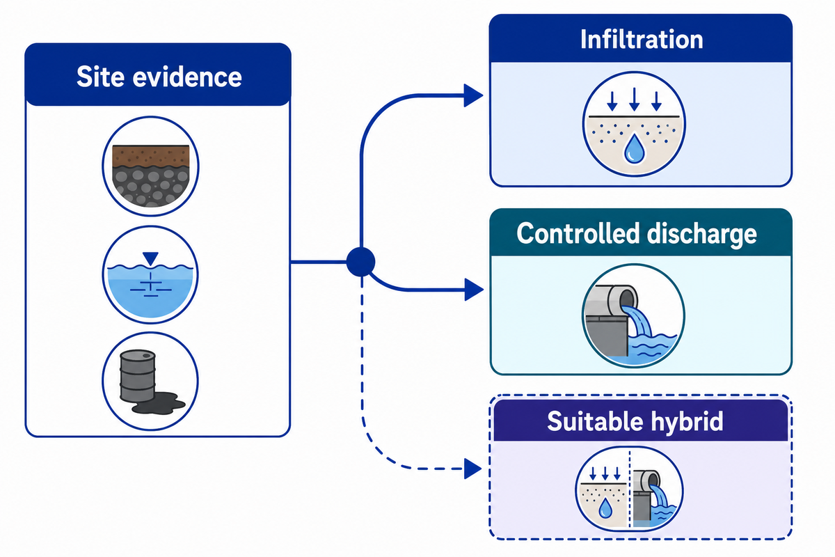
Attenuation limits the rate at which a scheme can discharge water, and infiltration sends suitable runoff to soil. A scheme can combine both functions for water management. The receiving route is determined by a ground investigation, groundwater, and pollution constraints, local drainage priorities and outfall acceptance. A shallow storage product can’t determine those constraints by itself.
Controlled-discharge attenuation
- Provide the required storage and outlet control.
- Resolve liner integrity and downstream conditions.
- Confirm the receiving destination and acceptance.
Infiltration or a suitable hybrid
- Establish infiltration performance at the proposed level.
- Assess groundwater and runoff pollution risk.
- Define any controlled outlet and exceedance route.
The Local Government Association’s drainage principles explicitly describe combined infiltration and attenuation. The U.S. Environmental Protection Agency’s infiltration basin factsheet also describes soil, groundwater and pollutant constraints. That open-basin source may be used to support suitability, but not to certify buried plastic storage systems.
Soil type alone can’t confirm infiltration performance at the proposed level. England’s 2025 National Standards state that an infiltration drainage base must not be within 1m of the maximum likely groundwater level. A shallow depth doesn’t remove that constraint. For other markets, identify the applicable local separation, testing and approval requirements before using any English figure.
| Observed condition | Action before selecting modules | Limitations / Not suitable for |
|---|---|---|
| Runoff water misses the inlet | Review surface collection and connection levels | More buried volume does not fix an unconnected route |
| Soil evidence is missing | Obtain site-specific infiltration investigation | Do not assign an assumed infiltration discharge |
| High groundwater is likely | Review separation, receiving route and buoyancy | England infiltration base within 1 m fails that stated criterion |
| Runoff presents pollutant risk | Resolve treatment and receiving protection | Void volume is not a water-quality treatment credit |
| An accepted controlled drainage outfall exists | Check outlet, levels and hydraulic design | Acceptance does not prove structural suitability |
| Above-ground measures are feasible | Check local preference and possible combined layout | Do not preselect buried storage without reviewing alternatives |
| Excavation space is restricted | Calculate the complete build-up against surveyed levels | A 150 mm module alone is not a 150 mm excavation |
| Traffic or construction plant loads apply | Request matched long-term and installed design evidence | No traffic approval follows from a short compression number |
| Buried modules cannot be reopened | Specify accessible sediment control and a maintainable route | Do not assume standard internal cleaning tunnels |
Consider whether underground storage is justified before comparing crate offers. Buckinghamshire’s developer guidance, last updated in December 2022, requires above-ground measures unless applicants demonstrate infeasibility, while allowing combined arrangements. This is a named local example, and shouldn’t be construed as a uniform global purchasing policy.
What is the difference between a soakaway and an attenuation tank?
A soakaway disposes of suitable runoff by infiltration into the ground, whereas a lined attenuation tank temporarily stores runoff for controlled discharge elsewhere. Both can use modular storage, but their wrapping, outlet and site assumptions differ. A partially infiltrating attenuation arrangement can combine soakaway and attenuation when supported by approved drainage design.
Compare attenuation and soakaway selection using the receiving conditions, then develop the infiltration detail with soakaway design guidance. Neither link replaces the investigation needed to justify infiltration at the proposed level.
England’s 1 m separation concerns the infiltration base and maximum likely groundwater, not the distance from finished paving to a crate top. England’s 1 m separation concerns the infiltration base and maximum likely groundwater, while a hybrid still needs its infiltration and controlled-outlet assumptions checked separately.
Check the whole depth budget, not just module height
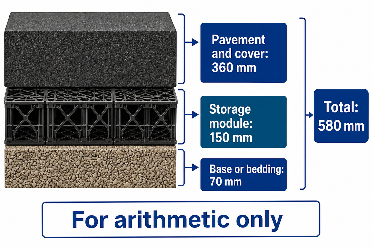
Total excavation can accommodate the complete build-up of a storage system with the approved pavement and cover, as well as the base or bedding. Compare that full build-up with surveyed utilities, inlet levels and groundwater before drainage installation begins. The construction layers must be taken from the approved system.
150-mm Excavation Myth
The 150-mm Excavation Myth assumes that the full allowable excavation of a module is the height of the module, and that the surrounding construction is outside the depth calculation.
For arithmetic only, take a 150 mm module, a combined 360 mm pavement-and-cover allowance and 70 mm beneath the module. The complete allowance is 360 + 150 + 70 = 580 mm. Of that illustrative total, 430 mm lies outside the module itself; none of these surrounding layer values is a recommended minimum.
| Depth item | Illustrative allowance | Evidence needed |
|---|---|---|
| Pavement plus cover above module | 360 mm | Approved finished-surface to module-top build-up |
| Storage module | 150 mm | Exact selected model and assembly |
| Base/bedding below module | 70 mm | Formation and base design |
| Total to formation | 580 mm | Surveyed level check for the complete assembly |
A designer reviewing a restricted-depth courtyard is offered a 150 mm shallow unit. Procurement compares the allowance offered with the available excavation allowance, but the drawing also requires space above and below the storage body. The designer requests the full cross-section, and checks that the delivering pipe can bring the runoff to the required level.
Using the illustrative 580 mm budget would expose a conflict wherever the available allowance were smaller, even though the module itself is only 150 mm high. The options would include an alternative pavement, layout, or drainage route, but only after the designers approve the changes. A shorter crate can improve one dimension without solving the inlet, formation or traffic condition.
The Philadelphia manual separates component design, manufacturer requirements and construction protection. For a wider site brief, use the shallow sub-base specification to organize the full arrangement. Protecting infiltration soil from compaction and constructing load-bearing bedding are different duties; specify each for its location.
How deep should a soakaway drain be?
A stormwater soakaway has no universal excavation depth. Establish the proposed level of infiltration, seasonal groundwater, the pipe invert level, usable storage, and total structural build-up. Local infiltration and separation factors limit the arrangement, and the approved assembly of a manufacturer determines the geometry; neither a shallow label nor a separation of groundwater figure answers the question of depth.
The illustrative 580 mm total contains a 150 mm module plus 430 mm of other construction. Replacing the module’s height changes only one input, so depth comparisons should use the full cross-section and the same finished-surface datum. Groundwater separation is then checked independently from the infiltration base.
Coordinate inlets, outlets and exceedance routes
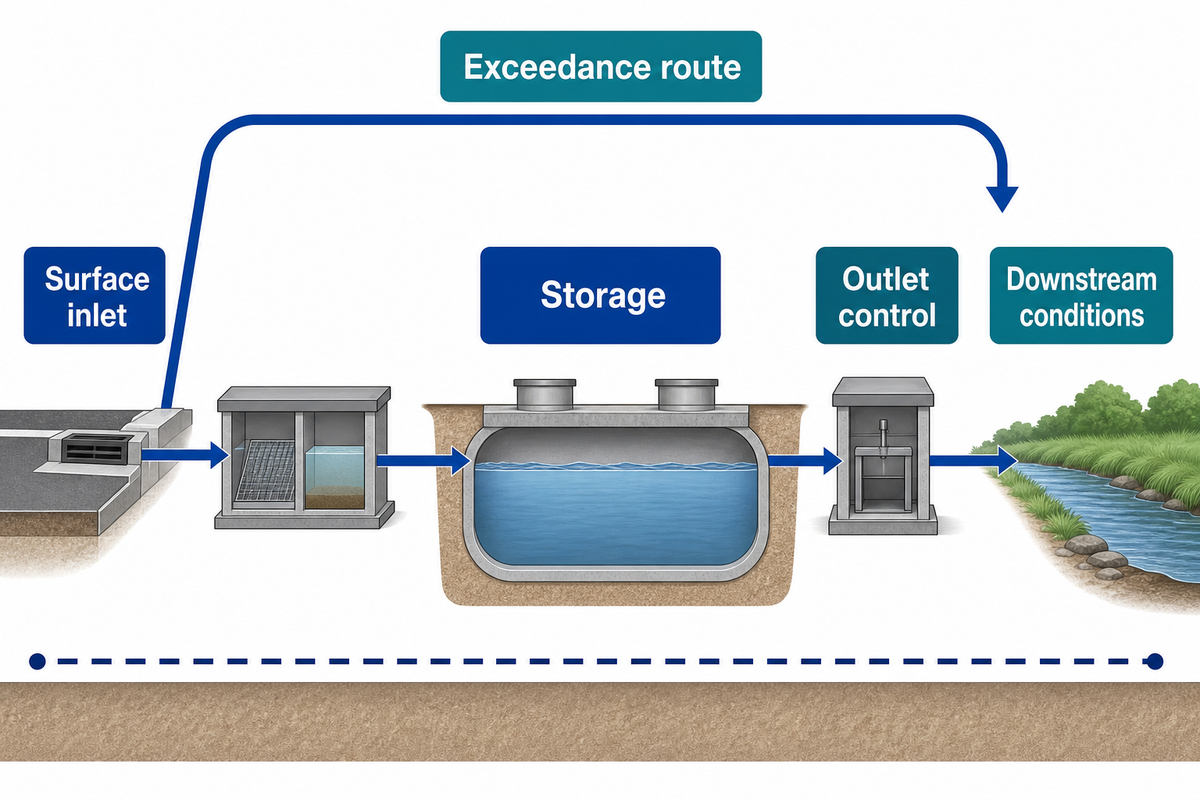
The functioning of the system depends on the water levels available between the scheme’s controlling elevations and the geometry of the modules. Coordinate the inlet, outlet control, downstream conditions and exceedance path before counting the whole void volume. Only then can the volume of the void be accounted for. The size of an external tank alone doesn’t determine the volume of water retained by the system.
Consider a simplified 20 m² storage footprint with 150 mm module height and a supplier void ratio of 95%. Nominal geometric voids would be 20 × 0.15 × 0.95 = 2.85 m³. If an illustrative 30 mm bottom band is unavailable to the selected operating storage calculation, the remaining 120 mm gives 20 × 0.12 × 0.95 = 2.28 m³.
Engineering note
The illustrative difference is 0.57 m³. The 30 mm band is an example assumption, not a prescribed deduction or tolerance; actual operating levels, internal components and other adjustments require the project hydraulic calculation. Use one surveyed datum for all inverts.
The storage relative to the lowest outlet level is shown in the Philadelphia manual, and the manufacturer’s void ratio is used to determine the available volume. Its local methodology is not a universal hydraulic sizing formula. The example separates dimensional arithmetic from the runoff, storm duration, inflow and allowable outflow needed to size a working system.
- Show where surface runoff from building and paved areas enters the collection network.
- Identify the control that limits onward water flow and the receiving waterway or network.
- Check whether high water downstream can affect the assumed discharge.
- Draw a safe exceedance route for water beyond the designed capacity or during blockage.
Review underground detention system design when detailing the complete controlled-discharge arrangement. A tank that holds a nominal amount of water still requires an accepted outfall, and a hydraulic design that covers the operating range. Collecting large volumes of water is of no storage use if the collection route bypasses the tank.
A 20 m² footprint at 95% void gives 2.85 m³ across an illustrative 150 mm height, but only 2.28 m³ across 120 mm. The 0.57 m³ difference shows why operating-level inputs belong beside the volume calculation; the example supplies no approved storm capacity or discharge rate.
Match structural evidence to the exact buried configuration
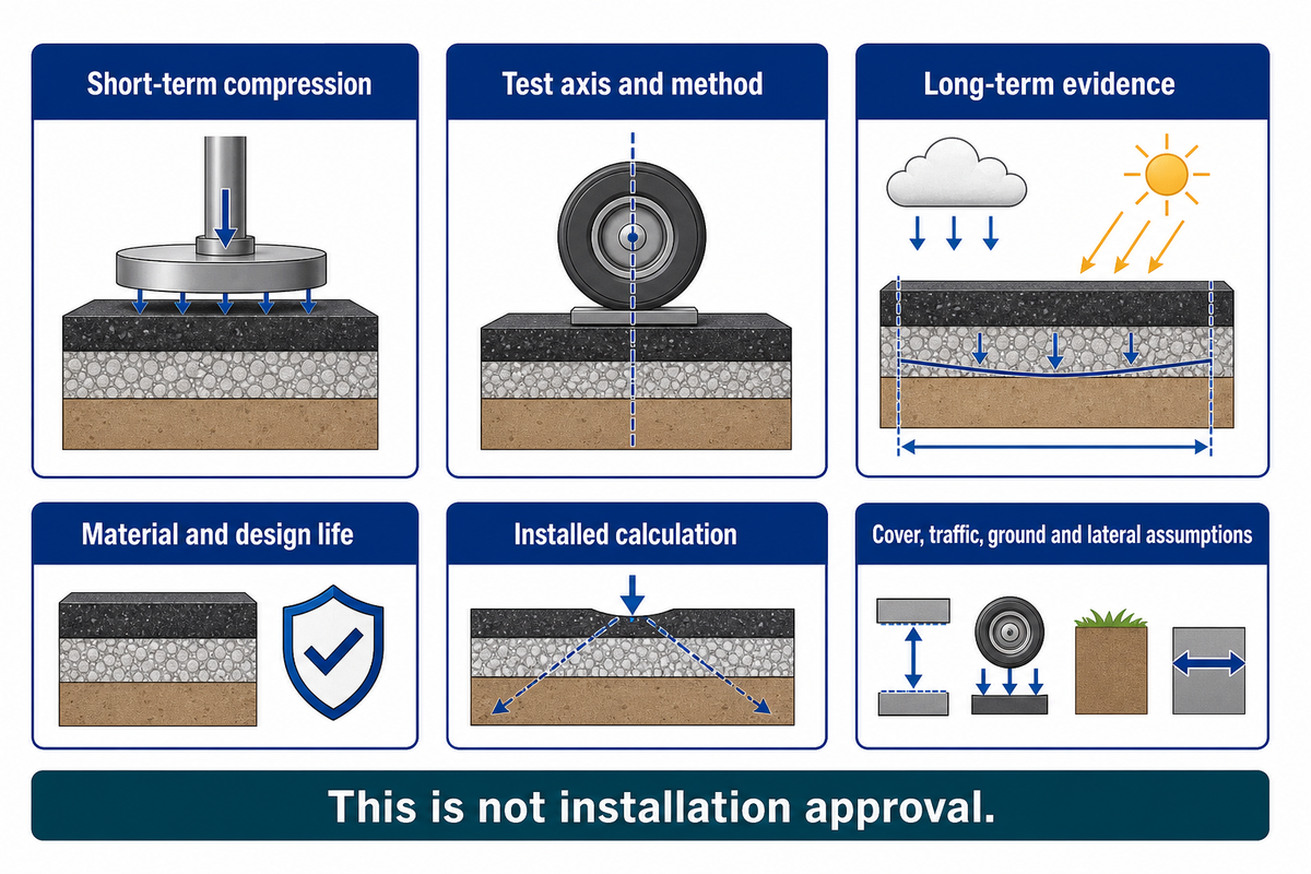
The long-term behavior of a buried module, and the conditions it’s installed in, determine its structural suitability. Provide evidence relevant to the assembly and design life of the modules. A short-duration vertical compression result cannot, by itself, become an allowable installed load or a universal cover depth.
The BPF Pipes Group’s November 2025 guidance distinguishes EN 17150:2019 short-term testing from EN 17151:2019 long-term testing. BPF represents manufacturers; its position on other guidance is an industry view, not a neutral ruling that one design method is universally invalid.
| Evidence type | Check on the exact offer | Limitations / Not suitable for |
|---|---|---|
| Model and assembly drawing | Module, base, interlocks and accessories | A different product generation or supplier |
| Nominal geometry | 1000 × 500 mm footprint for the quoted ARW-SA unit | Proving complete excavation or usable project volume |
| Published void ratio | 95% ARW-SA vendor statement versus model-specific alternatives | Independent certification or treatment credit |
| Short-term compression test | Test axis, conditioning, specimen and method | Direct conversion to long-term installed loading |
| Long-term compression evidence | Selected material, model and design-life basis | Resolving every site or interface risk alone |
| Installed structural calculation | Cover, traffic, ground and lateral assumptions | Unassessed construction-plant movements |
| Groundwater and buoyancy assessment | Water levels, empty-system condition and restraint | Assuming a lined tank suits every groundwater condition |
| Backfill and formation specification | Materials, placement and applicable project limits | Substituting an arbitrary bedding allowance |
| Membrane and geotextile specification | Purpose, protection and interface detail | Claiming coverage by a crate structural standard |
| Maintenance and access layout | Reachable sediment traps, controls and cleaning route | Assuming a sealed module can be opened later |
The BSI public scope of PD CEN/TS 17152-4:2025 describes structural design of modular systems. It doesn’t include lateral loads from adjacent structures and embankments, and the influence of trees, among others. Geotextiles and Geomembranes are also outside the scope.
These exclusions must be addressed on an individual basis, and don’t mean the module shouldn’t be used. A supplier citing the guidance should identify the version and assumptions used, then show how excluded site factors are resolved. Only the public scope of the guidance has been reviewed, not the full (paid for) version.
When not to buy a shallow tank from brochure data alone
The purchase should be held if the proposed arrangement doesn’t have a defined receiving route or if it doesn’t have a usable volume or complete cross-section. A module in a brochure may identify a candidate module, but a commitment to a quantity of that module may leave the project with storage that can neither be connected nor approved for the location where it’s needed.
A vertical test result says little about an adjacent embankment’s lateral effect unless that effect is included in the assessment; naming the 2025 guidance doesn’t close its listed exclusions. Who owns the calculations? What document addresses the groundwater, formation and temporary construction conditions?
Maintenance can also change the buying decision. If the chosen module can’t be reopened, the proposed sediment-control and cleaning arrangement must have a reachable physical route rather than a promise to inspect later. The England national standards’ maintenance provisions require accessible sediment control and consideration of blockage. These are reasons to complete the scheme before ordering, not evidence that every shallow storage product fails.
Keep sediment control and maintenance access visible
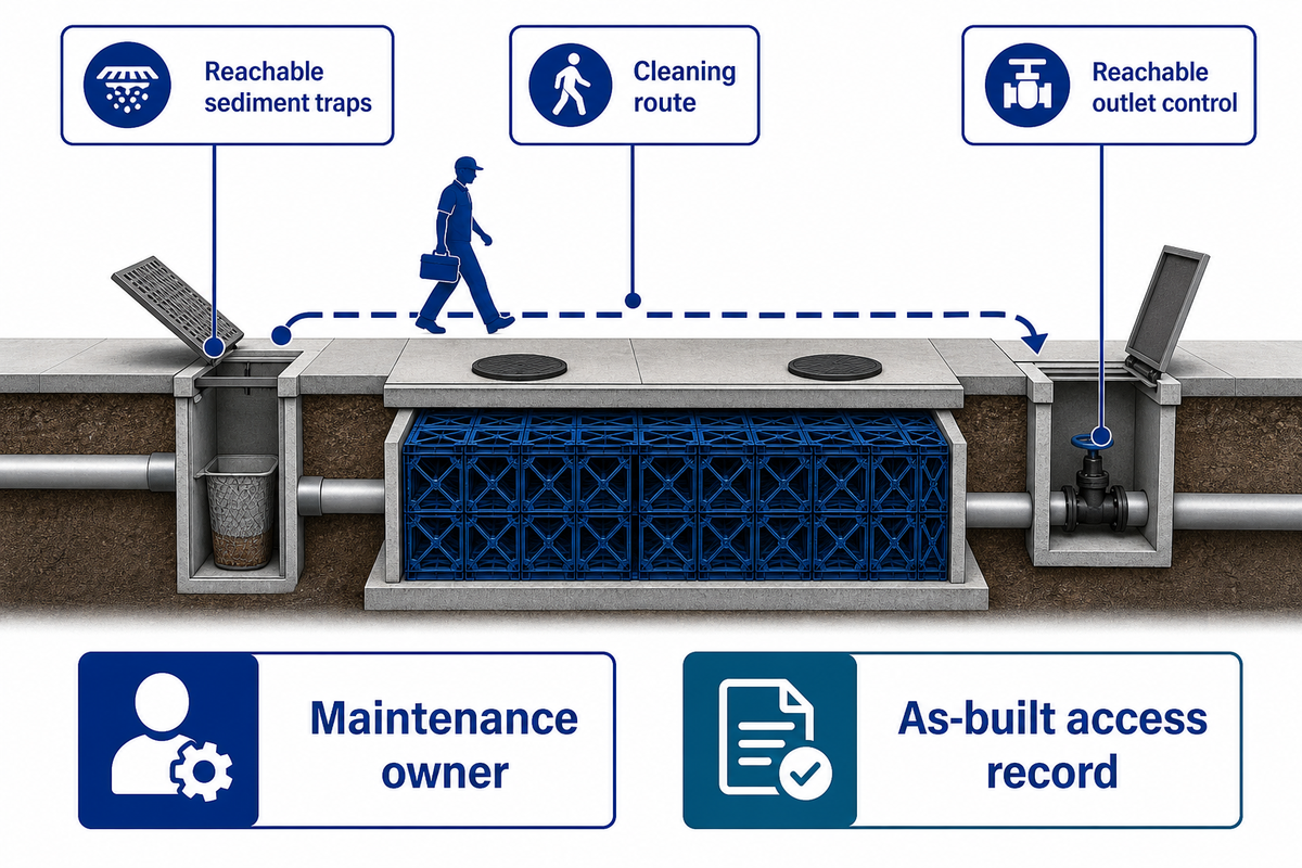
Shallow storage requires sediment control and access for maintenance before burial. Protect storage and infiltration surfaces with appropriate pretreatment, and give operators access to relevant traps, inlets and controls. The method of construction of the modules determines the methods for internal inspections and cleanings.
The 2025 standards of England, clauses 7.13 to 7.16, cover sediment, access for removal and failure due to blockage. Storage voids by themselves don’t guarantee complete water quality treatment. A tank can’t treat polluted rainwater to make it safe for reuse by retaining it.
“The surface water drainage design shall ensure sediment, detritus and debris can be easily removed from the system.”
AQUA states that its ARW-SA module, when assembled, isn’t to be reopened. Request the actual inlet, pretreatment and maintenance arrangement for that model. Don’t infer standard CCTV tunnels, unrestricted internal cleaning or easy dismantling from another manufacturer’s Geocellular drawings.
A procurement lead receives an offer covering shallow modules and wrapping materials, while the operator asks how accumulated sediment will be removed after paving is complete. The number of modules answers a supply question; it doesn’t indicate where a cleaning vehicle can be positioned, or which trap can be emptied. The lead returns the maintenance layout for completion before approving the offer.
The designer identifies suitable inlet traps and outlet control chambers, and confirms that the intended cleaning method can access the affected component. The contractor records those locations and protects the system from construction sediment before handover. If a proposed cleaning route can’t physically reach the storage, the team needs to modify the plan rather than assure a sealed unit will be opened.
Do
- Specify reachable sediment traps.
- Show the inspection and cleaning route.
- Name the maintenance owner.
- Retain the as-built access record.
Do not
- Treat void ratio as pollutant removal.
- Assume every crate has a cleaning tunnel.
- Bury unresolved access points.
- Copy another system’s maintenance interval.
Maintenance frequency is shown in the approved plan and operating instructions, and is reviewed when there’s a change in sediment loading or drainage conditions. Sediment traps only help keep water paths open when they’re cleaned and serviced. Where surface water remains after a storm, inspect accessible collection and controls before attributing poor drainage solely to inadequate tank volume.
Specify AQUA ARW-SA as a separate shallow option
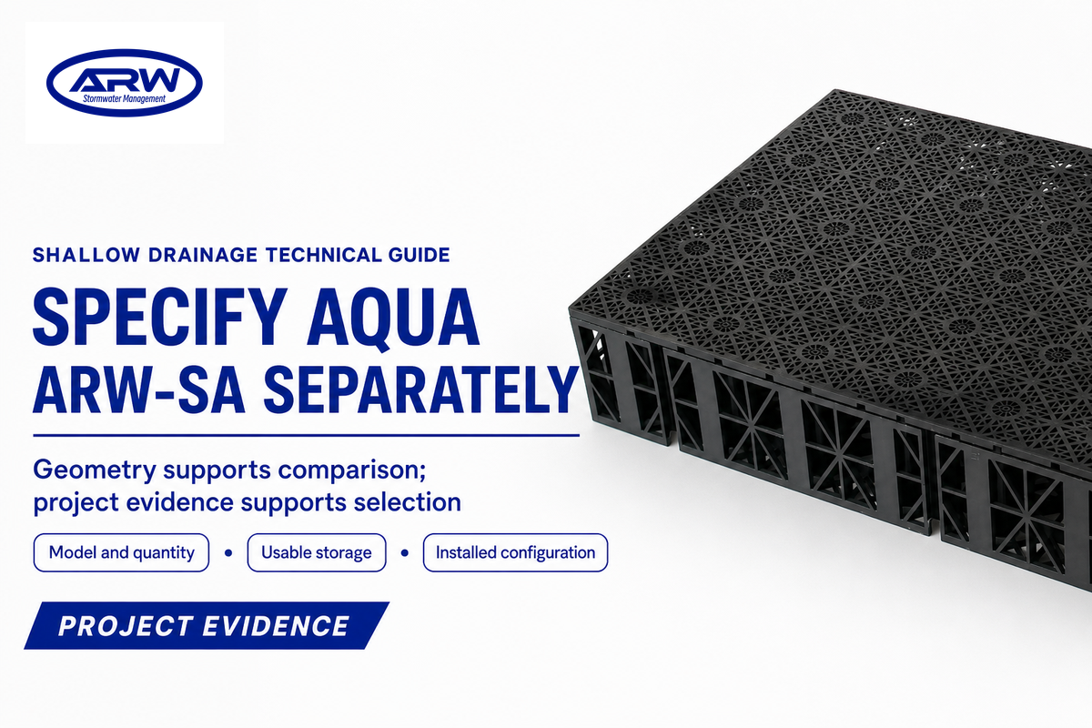
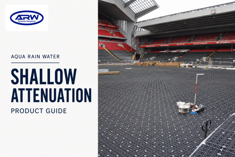
AQUA publishes ARW-SA shallow modules with a footprint of 1000 × 500 mm and four nominal heights with a void ratio of 95%. The supplier values can be used to make a preliminary geometric comparison, and the project still needs to complete hydraulic and structural design. ARW-SA is a separate offer from Naylor’s AquaVoid with its own assembly and evidence.
| Module height | External volume | Geometric void volume at 95% | Per m², one layer |
|---|---|---|---|
| 85 mm | 42.5 L | 40.375 L | 80.75 L/m² |
| 150 mm | 75 L | 71.25 L | 142.5 L/m² |
| 200 mm | 100 L | 95 L | 190 L/m² |
| 250 mm | 125 L | 118.75 L | 237.5 L/m² |
For the 150 mm option, 1.0 × 0.5 × 0.15 = 0.075 m³ external volume; multiplying by 0.95 gives 0.07125 m³, or 71.25 L. Two nominal units cover 1 m², giving 142.5 L/m² before project-specific adjustments. This calculation does not deduct inaccessible levels and doesn’t consider connectors or other features in the approved arrangement.
AQUA’s current product literature shows top and bottom panels clipped around interior supports with horizontal interlocks between modules. Ask AQUA to identify the quoted assembly and supporting documents; ask the responsible designer to establish the installed configuration and acceptance criteria. A complete system comprises the storage body and the specified collection, receiving and maintenance interfaces.
Keep membrane and geotextile supply distinct from module manufacture. AQUA’s product page describes those supporting materials as procured items, so an injection-moulding capability does not establish the membrane producer or its test results. Define the material and its role in the system.
RFQ checklist: copy these questions into the quotation request
| Parameter | Required project input | Why it matters | How to verify |
|---|---|---|---|
| Model and quantity | Exact height and assembly | Geometry and connections change | Current drawing and itemized offer |
| Storage | Required usable m³ and operating levels | Nominal void is not the whole calculation | Hydraulic design and module schedule |
| Build-up | Approved layers in mm and surveyed levels | Complete excavation must fit | Project cross-section |
| Loads | Traffic, ground and construction assumptions | Short tests do not approve installation | Matched test evidence and structural calculation |
| Wrapping | Liner or infiltration route and material identity | Material role and source differ | Supplier specification and interface detail |
| Maintenance | Access locations and cleaning method | Assembled modules cannot be assumed reopenable | Physical route and maintenance plan |
A 250 mm ARW-SA unit is 125 L external volume, and calculated void volume is 118.75 L at the vendor’s 95% ratio. That taller option changes geometric capacity to 237.5 L/m² per layer; it does not establish permission to reduce cover or to omit the hydraulic-level calculation.
Industry Outlook: use current drainage standards to change the procurement brief
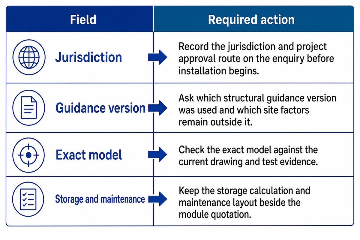
Current drainage guidance takes the whole scheme rather than the module brochure as the starting point for a 2026 purchase. England’s 2025 national standards and 2025 structural guidance address different duties and scopes. Identify the governing jurisdiction, current documents and outstanding interfaces, before treating a specification reference as definitive evidence.
For developments subject to England’s standards, include infiltration suitability, receiving destination, sediment removal and maintenance in the approval brief. The national publication doesn’t give a universal shallow-tank cover or load rating. A buyer working elsewhere should ask which local document controls the same decisions and whether the offered design actually uses it.
Structural guidance has changed. BSI’s public entry dates PD CEN/TS 17152-4:2025 to 31 July 2025, while CIRIA’s guidance catalogue distinguishes C753, The SuDS Manual, from C737, the structural and geotechnical design publication. Older supplier documents may incorrectly name a guide or state a period prior to the publication of the referenced test standards.
- Record the jurisdiction and project approval route on the enquiry before installation begins.
- Ask which structural guidance version was used and which site factors remain outside it.
- Check the exact model against the current drawing and test evidence.
- Keep the storage calculation and maintenance layout beside the module quotation.
A purchasing lead comparing a familiar legacy sheet with a current offer should ask for a model-to-document match before accepting copied values. Naylor’s current table and family overview illustrate the need: specific 95.5% and general 96% void statements should retain their stated contexts. The same discipline applies to AQUA’s separate 95% vendor figure, without claiming that those percentages prove comparative performance.
No reproducible public demand series was established for this exact branded query, and broad commercial stormwater forecasts were not used to justify a purchase. Actionable 2026 trends include scoped drainage guidance and structural guidance. Before quantities are fixed, unresolved site conditions and the named versions must be reviewed with the responsible designer.
For England infiltration design, the 1 m groundwater separation should enter the receiving-route brief independently of any module height. Leaving that elevation separate from the 2025 structural guidance prevents an inappropriate standard list from being mistaken as approval of the soil, liner, outlet, and installed load conditions.
Frequently asked questions
What is a shallow geocellular drainage system?
Underground modular storage arranged with a reduced-height storage body.
A shallow geocellular drainage system uses interconnected modular units below ground to provide void space for stormwater. The shallow description refers to the storage body’s geometry, not a guaranteed excavation depth. Infiltration, controlled discharge or a suitable hybrid needs its own site evidence, while surface collection, pretreatment, access and the surrounding structure complete the scheme.
Is AquaVoid the same as AQUA ARW-SA?
No. The products are separately marketed by Naylor and AQUA.
AquaVoid is Naylor’s stormwater storage family; ARW-SA is AQUA’s shallow module range. Similar storage purposes do not establish shared ownership, licensing or interchangeability. Use each supplier’s exact model, assembly drawing and applicable technical data, then have the project design checked against those inputs. No relationship between the two product families was established in the reviewed public material.
Does a 150 mm module need only 150 mm of excavation?
The complete installed build-up determines the excavation allowance.
The module occupies only part of the finished-surface-to-formation depth. Pavement and structural cover lie above it, while the approved base or bedding lies below. Incoming pipe levels and groundwater can add constraints that a module-height comparison misses. Obtain the selected system’s full cross-section and compare all elevations with the site survey before treating a shallow option as feasible.
When should I have my drainage system checked?
Follow the approved maintenance plan and investigate unusual ponding.
Inspect accessible inlets, sediment traps and outlets after changed drainage behavior. Record the observations and refer unresolved collection, capacity or outfall questions to the responsible designer.
How long does an attenuation system last?
A service-life claim needs matching long-term evidence and project assumptions.
No single lifespan applies to every shallow attenuation system. The structural assessment should state the design life and use suitable long-term evidence for the selected material and assembly. Ground conditions, sustained and lateral loads, groundwater, construction damage and later loading changes can affect the installed asset. Maintenance must keep collection points, sediment traps and controls serviceable. Request the offered model’s technical basis and operating instructions, then check that the design assumptions remain valid throughout use. A supplier’s lifespan statement for another model does not establish the life of the quoted system.
Looking to improve your property’s drainage system?
Diagnose the receiving route and collection problem before buying storage.
Survey the problem, inspect accessible components and obtain a site-specific design. Extra modules alone cannot resolve an inlet or outfall mismatch.
Discuss an ARW-SA shallow storage enquiry

Send AQUA the intended model, required usable storage, site cross-section, loading assumptions and maintenance layout. Request the matching supply documents, then resolve project design and approvals with the responsible professionals.
Technical scope: The technical scope of this guide incorporates public manufacturer specifications and scoped drainage guidance. Illustrative calculations teach dimensional checks; they are not a site design, third-party product certificate or reported AQUA installation. Model-specific load, cover, operating storage and maintenance decisions require the appropriate project evidence.
References & Sources
- Geocellular storage systems, CIRIA/Susdrain.
- Subsurface infiltration manual, Philadelphia Water Department.
- Sustainable drainage principles, Local Government Association.
- Stormwater best management practice: infiltration basin, U.S. Environmental Protection Agency, 2021.
- National standards for sustainable drainage systems, England government, 2025.
- Design standards for drainage components, Buckinghamshire Council, guidance updated 2022.
- Design guidance for geocellular systems, BPF Pipes Group, November 2025, manufacturer-association position.
- PD CEN/TS 17152-4:2025 public scope, British Standards Institution.
- CIRIA guidance catalogue, CIRIA/Susdrain.