Get in touch with AQUA Company
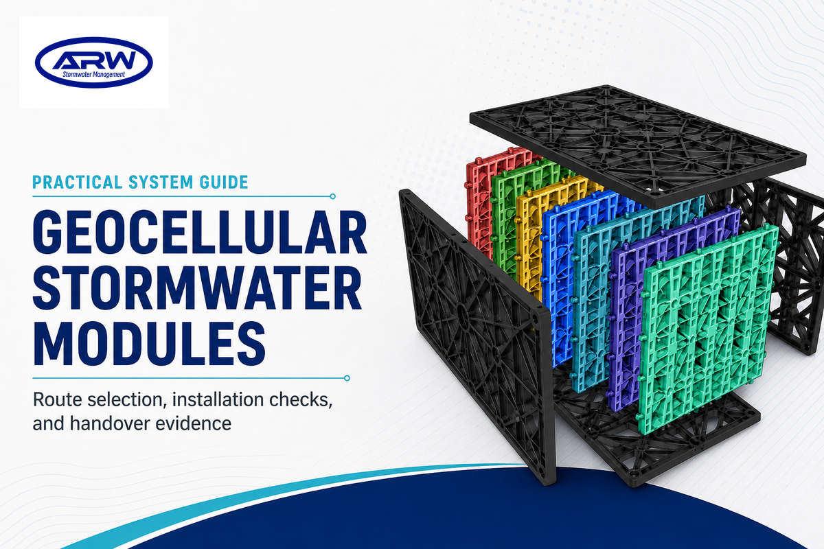
Geocellular Stormwater Modules: A Comprehensive Guide to Selection, Design and Handover
UPDATED SEPTEMBER 2026
AQUA Rain Water Educational Guide
Geocellular stormwater modules are just some elements in a drainage system.
The short answer
- Define your water management requirement before you assess the module labels, be it detention, attenuation, infiltration, or reuse or a combination of these.
- Site evidence for the soils and groundwater, the type and amount of inflow and outfall control, loading, silt, and the requirements and preferences of the local authority, should be collected.
-
Separate storage from treatment. Pretreatment, sediment control, inspection access and maintenance responsibility should be addressed separately.
- Prior to the system being buried freeze the responsibilities for inlet and outlet, wrapping or lining, access, edge conditions and construction.
- Accept the work through records, photographs and levels, and named owners, rather than a Universal Performance Standard.
- Use the commercial solution page when ready to transform an approved brief into product configuration and quote.
For a review of the current range of Geocellular Stormwater modules and a request for a system design configuration, visit the Geocellular Stormwater Modules product page. This article has a different purpose, it’s a practical planning and handover guide for the decisions which should be made prior to finalizing a product schedule.
Terms can vary based on the location. Products like “stormwater tank” and others, may serve similar functions, but they don’t validate site readiness. Keep the requests, relevant authorities, design assumptions, and project documentation. In a broader context of stormwater management, design the expected peak flows and storage volumes separately and don’t consider either case as a module specification.
What Geocellular Stormwater Modules Actually Do
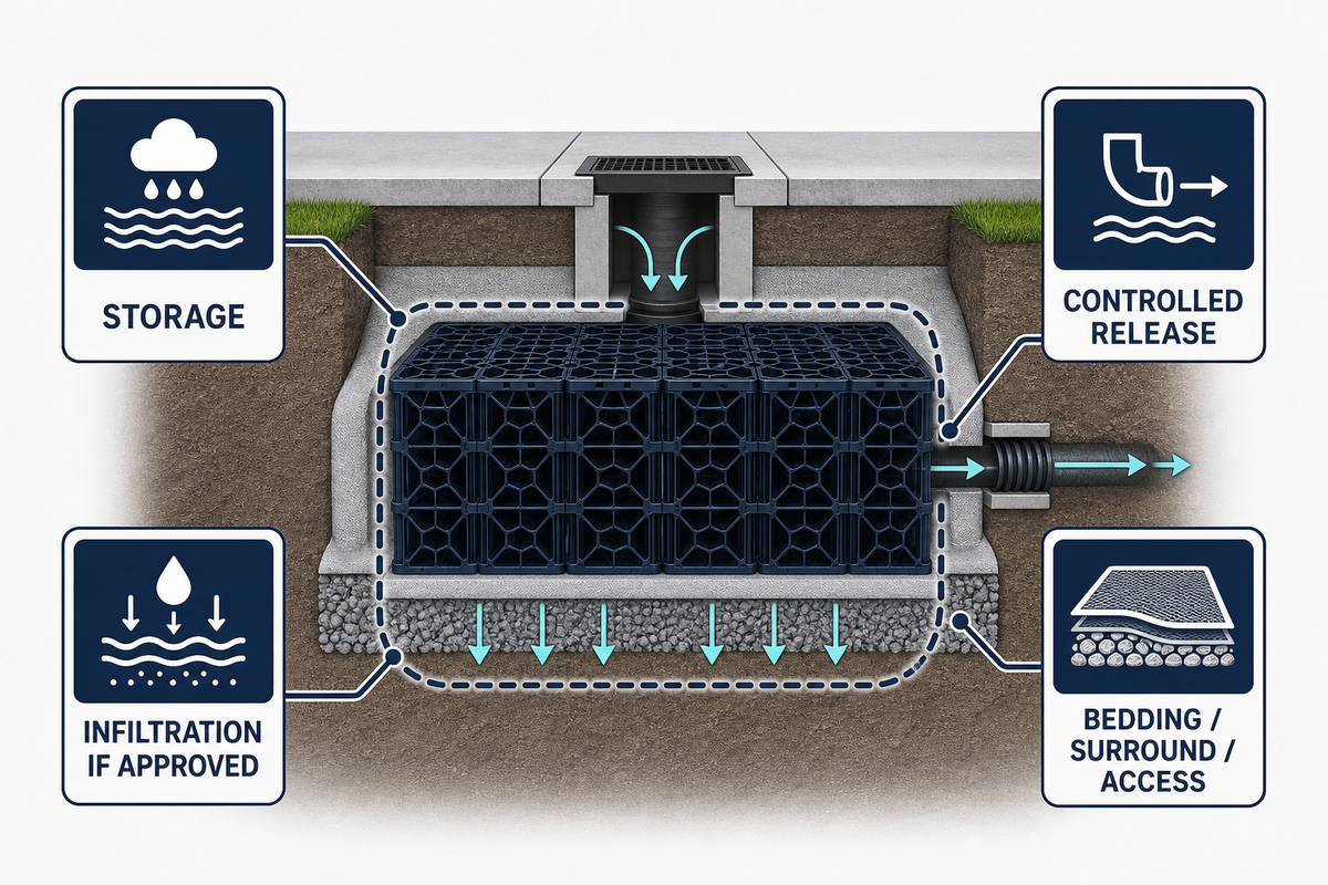
A Module System is designed to create a planned underground space for temporary storage of water, controlled release of stored water, or allowing water to infiltrate provided the ground and approvals permit that. See SusDrain’s geocellular storage guidance for storage and infiltration context. The modules are designed to be surrounded by the interfaces (as shown on the approved detail): bedding, surround, geotextile, geomembrane, pipework, access, inspection, and cover. Thus, the module is a part of a hydraulic and structural assembly.
Detention and attenuation relate to water storage and the controlled release of water to an outlet. Designs involving infiltration or soakaways require assessment for load separation, soil characteristics, the risk of pollution, and local conditions. A tank with a lining is capable of water storage without infiltration, whereas an infiltration system may require multiple checks and protective measures. Don’t select a route based on the word ‘storage’.
The term ‘high void space’ also requires additional explanation. A void with nominal description doesn’t describe how the system would behave during the construction process under the cover, loading, groundwater, sequence of construction, access, and inspection. Ask the designer to relate each performance statement to the model, load grade, test method, limiting conditions, and approval package for which the performance applies.
The 4-Route Stormwater Module Route Matrix
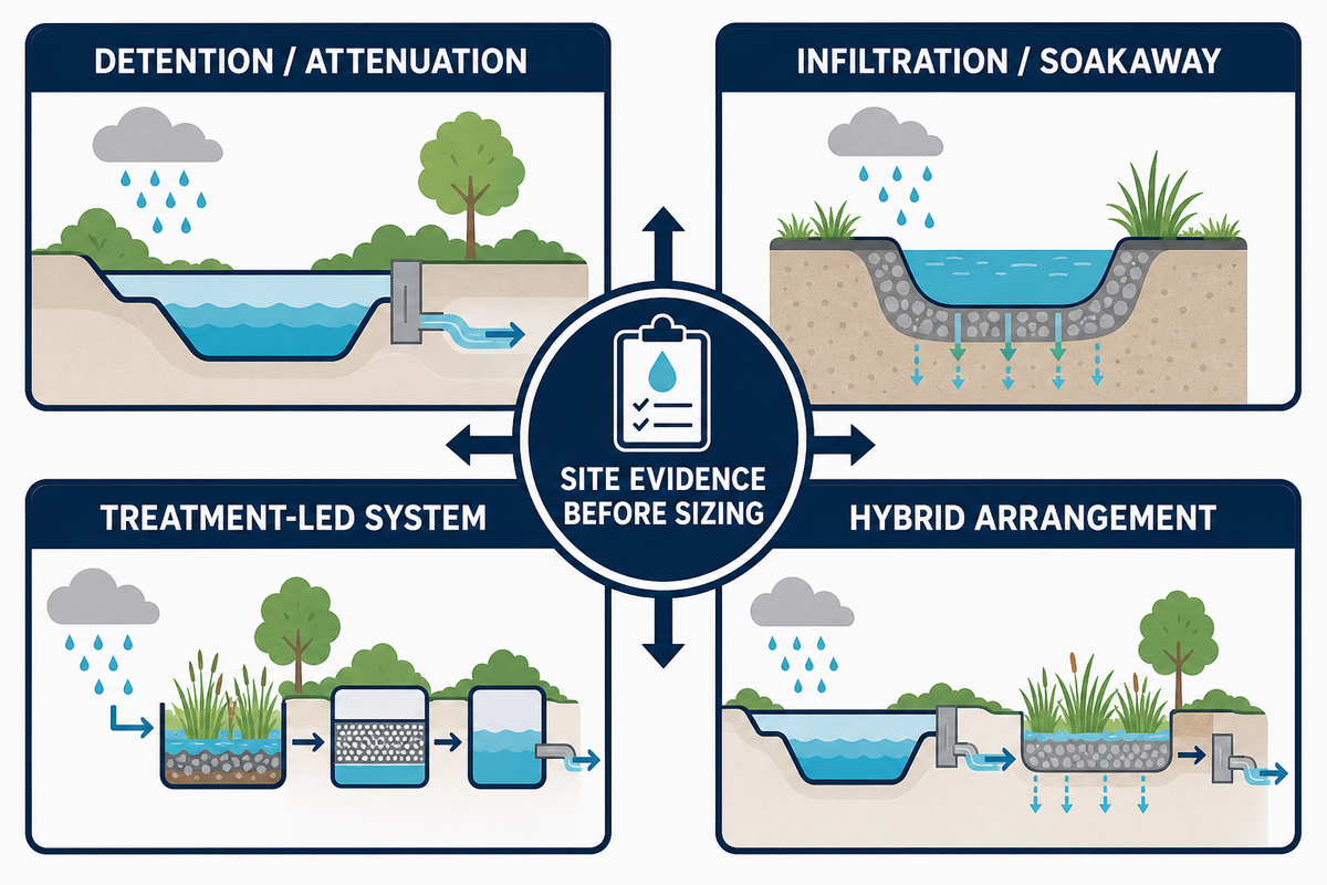
The Stormwater Module Route Canvas is designed for an early design gathering to help provide visualization of the layout and setup of the stormwater systems. See Hydro International’s geocellular design guidance for construction-coordination context. For terminology alignment, the stormwater terminology route builder can be used before the design meeting. These geocellular systems still need site evidence before sizing. It shouldn’t be used in lieu of hydraulic calculations or a local authority review. For a public planning perspective, see GOV.UK’s flood risk and sustainable drainage guidance.
| Route category | Question to answer | Evidence to attach | Common boundary |
|---|---|---|---|
| Detention / attenuation | What inflow is held, and where and how is it released? | Hydraulic model, outlet control, overflow route, approval notes | Storage does not itself set the permitted discharge. |
| Infiltration / soakaway | Can the ground accept the intended water without creating a new risk? | Infiltration testing, groundwater observations, soil and pollution review | Module labels do not prove soil suitability. |
| Treatment-led system | Where are sediment, hydrocarbons, litter, or other pollutants intercepted? | Pretreatment schedule, maintenance access, water-quality objectives | Geocellular storage is not automatically a treatment device. |
| Hybrid arrangement | Which water reaches each component, and which component owns each duty? | Flow diagram, interfaces, bypass and overflow logic, responsibility matrix | Interfaces can fail even when individual components are suitable. |
| Pretreatment train | Where are sediment and litter intercepted before storage? | Catchment pollutant review, silt-trap detail, cleaning route | A storage body is not automatically a treatment device. |
| Rainwater harvesting overlay | Is stored water intended for a defined non-potable use? | End-use, treatment, signage, backflow and public-health notes | Storage volume does not equal treated or potable water. |
| Flood-resilience overlay | What happens during an event beyond the selected design case? | Emergency overflow, safe exceedance path, owner response | A module system does not remove all flood risk. |
| Retrofit or constrained site | Can the system be built around existing road infrastructure and utilities? | Survey, utility records, staging plan, temporary traffic plan | A nominal footprint does not prove buildability. |
The table’s evidence signals are not optional data decoration: rainfall basis, inflow and outfall control, soil and groundwater, pollution risk, cover and traffic, utilities and access, ownership, and maintenance access can each change the route or handover duty.
The route should be reviewed by the individual responsible for drainage approvals, the civil or structural designer, the stormwater system installer and the potential system owner or operator.
| Evidence signal | What may change | Route consequence | Action before sizing |
|---|---|---|---|
| Rainfall basis | Catchment response and peak inflow | Storage capacity and outlet duty | Confirm the authority event and time basis |
| Inflow and outfall | Peak flow and tailwater | Flow-control setting | Map discharge and exceedance |
| Soil conditions | Infiltration rate and groundwater | Geocellular infiltration feasibility | Arrange site tests |
| Groundwater level | Buoyancy and separation | Lined tank or infiltration route | Record seasonal observations |
| Pollution risk | Pretreatment duty | Stormwater infiltration safeguards | Define pre-treatment and maintenance |
| Cover and traffic | Load path | Structural integrity checks | Confirm cover and load evidence |
| Utilities and access | Build sequence | Stormwater management system footprint | Reserve access and lifting route |
| Owner and authority | Acceptance records | Site-specific handover | Name the approver and operator |
| Maintenance access | Cleaning and inspection | Long-term operation | Record reach, trigger and owner |
If the team is unable to describe the route with one paragraph, it’s premature to begin comparing module system quotes. Productive meetings end with unanswered questions. It’s a false assumption that the deepest or largest module system is the safest.
The methodology avoids cannibalization of information and conversion content. The solution page can house modeling options and configurations, documentation, and quote requests. The guide should cover the logic that helps the client identify each of the input gaps.
Start with Site Evidence, Not Module Labels
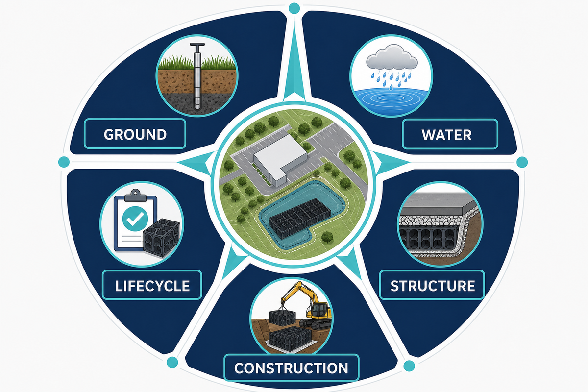
Before the layout is drafted, the controlling evidence for the path should be collected. Compare the evidence with King County’s surface-water design manual as an example of current authority documentation. A stormwater project input checklist helps the team keep those site records together. Begin with the boundary and inflow assumptions: roof, pavement, landscape, and surface runoff; upstream piping, emergency overflows, and any connections. Determine the discharge point, and legal and physical constraints, as well as if there’s a safe and legal discharge of overflow. Climate change and flooding, along with the placement of the construction and the nature of the road, change the response even in the absence of changes to the stored system. Because urbanization increases impervious area, the flow control data and infiltration hydrology shouldn’t be copied from adjacent sites.
- Ground: soil profile, infiltration, groundwater observations, sensitivity to contamination or pollution, and soft or variable zones.
- Water: contributing area, design events as selected by the authority, inflows, outfalls, bypass, overflows, tailwater.
- Structure: cover, traffic or construction loads, proximity of foundations, utilities, sensitivity to settlement, and constraints to access.
- Construction: excavation support, control of water levels, lifting, sequences, exposure to the weather, temporary traffic control and who can authorize a hold point.
- Lifecycle: sources of sediment, inspection points, the method of cleaning, confined space risks, budget for maintenance, and the owner following handover.
Don’t convert examples from another project into universal values. An indicated cover depth, load category, void percentage, flow rate, service life, inspection interval or temperature shouldn’t be considered without the associated product, test, soil, boundaries and jurisdiction. Where a value isn’t specified, enter “to be confirmed by the project designer” as opposed to using an arbitrary value.
For a brief that’s traceable, each approved input should be assigned to its unit. These include area in meters squared, cover in millimeters, pressure or load in kPa, flow rate in liters per second, temperature in °Celsius, inspection time in hours, response time in days and sampling in percent. Just because these are used as default design values, doesn’t mean they may be used without proper authorization. Where a rainwater harvesting duty, or a control of flow, is considered provisional, this should be indicated.
The ‘System Evidence Compass’ is a straightforward tool to evaluate briefs: ‘known’ means an approved record is available; ‘assumed’ means the team has a hypothesis; ‘missing’ means the decision can’t be prematurely made. A missing groundwater observation, an assumed outfall level, and a known access route shouldn’t be treated as a single input that can be relied upon to design.
Storage, Attenuation and Infiltration Decisions
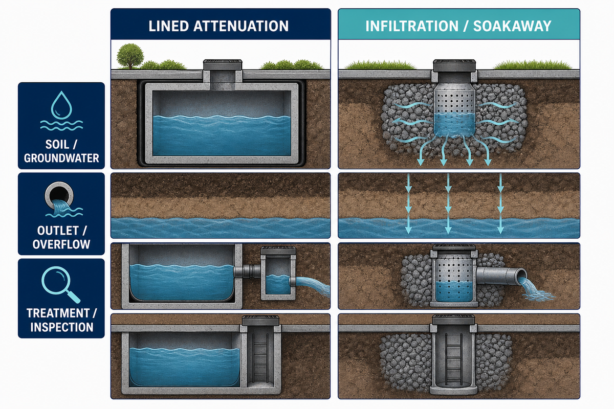
Detention or attenuation is a controlled volume problem. For the storage and discharge distinction, see SusDrain’s geocellular storage reference. A preliminary stormwater storage layout can then test whether the route and storage capacity are coherent before product configuration. Water enters, is stored, and a nominated route allows for exiting. The design team must show what they’ll control in terms of outlet, upstream restraint, overflow, and the evidence that shows the system performs as intended. A storage module shouldn’t replace the need for consideration of the Upstream conveyance and Downstream capacity.
Infiltration is a decision about ground and water quality and a storage decision. Soil layers vary at a site; groundwater can rise and a route that works for clean roof runoff can be unsuitable for sediment or pollutant runoff. Establish the requirements of the authority, the separation criteria, pretreatment and a monitoring plan, prior to accepting an infiltration route.
A lined attenuation tank and an infiltration or soakaway system can look similar in a catalogue photo, while design details vary significantly. Wrapping or lining, drainage layers, access points, outlet controls and acceptance records aren’t interchangeable. Each function of the interface should be named in the drawing.
Decision prompt
If the same module arrangement is proposed for both infiltration and lined attenuation, which assumptions changed: soil, groundwater, lining, outlet, treatment, inspection, structural review, and approval. Clear answers are more useful than a larger nominal storage volume.
Where reuse or rainwater harvesting is included in the brief, separate the under ground storage from the public health and non-potable-use categories. Collection, treatment, and access, as well as backflow protection and control, may need to be contracted in separate work packages. Don’t refer to the stored water as “treated” since the module was merely a storage element.
Treatment, Pretreatment and Water-Quality Boundaries
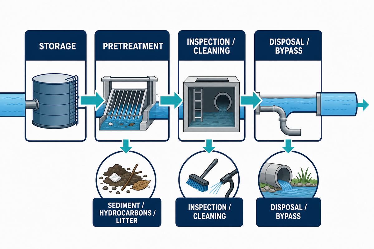
The most important adjustment in geocellular design is the segregation of storage and treatment. Hydro International’s design guidance also frames storage interfaces as a coordination issue. Modules have a storage function; they don’t remove sediment, hydrocarbons, litter, nutrients, pathogens, and dissolved organics or contaminants to an acceptable level. Water quality objectives require a named treatment infrastructure and an explicit treatment framework for each element.
Silt traps, catchpits, filters, separators, screens, swales, and other approved measures can be used for pretreatment. The most appropriate measure for a particular catchment and authority will be selected. A pretreatment structure will require access, inspection, cleaning, disposal, and bypass control. Filling up with sediment can cause a downstream module to have a loss of effective capacity even though that module hasn’t changed.
- Determine the actual site pollutants and sediment sources.
- Each water quality responsibility is allocated to a component with a defined maintenance responsibility.
- Check whether inspection can be done without either an unsafe entry or a destructive excavation.
- Procedures for isolation and/or bypass and restart under abnormal conditions are to be documented.
- Keep the claims for storage, treatment, and discharge in the specification and handover documentation distinct.
This boundary also contains procurement language. “Suitable for stormwater storage” isn’t the same as “certified treatment performance.” Should a supplier present a test report or certificate, record the exact product, test, scope, issuing body, and validity. Internal compression testing or batch sampling is acceptable as a process indicator; however, it can’t be renamed as an independent certification.
The Pre-Burial Decision Register
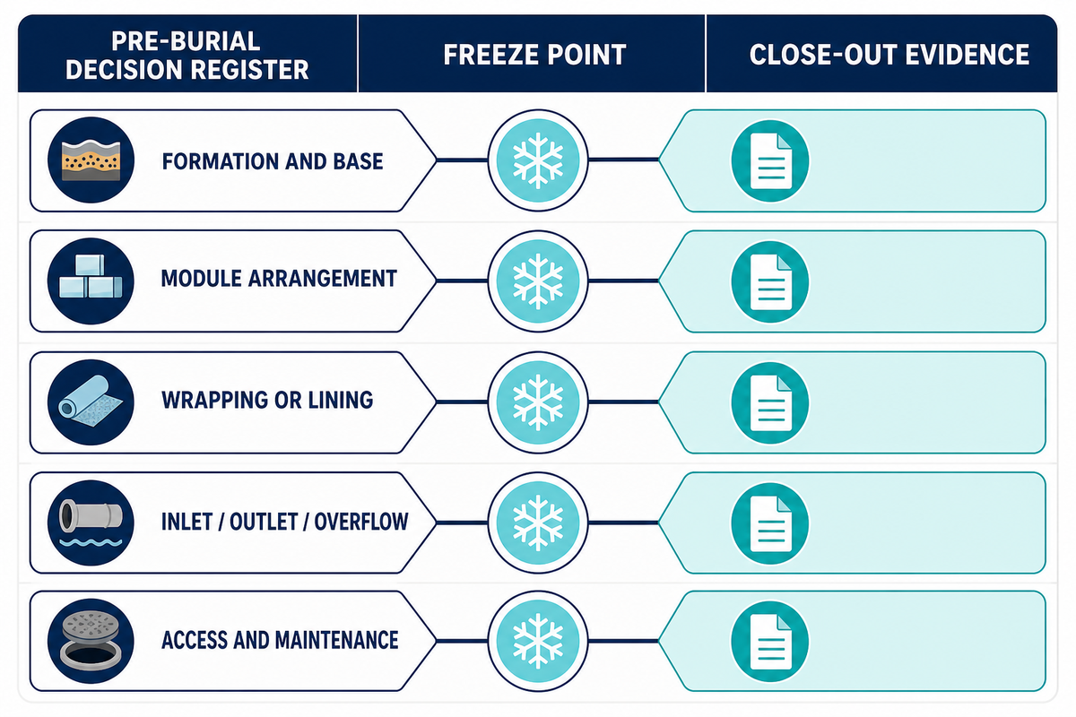
The Pre-Burial Decision Register is the place in the process where design intent becomes construction record. The construction-coordination prompts are consistent with Hydro International’s geocellular design paper. It’s to be reviewed prior to the placement of the first module and is to be updated when an interface is changed. The register isn’t a substitute for a drawing, it’s a concise verification that the drawing, method statement, inspection plan, and responsibilities are aligned.
| Register item | What to freeze | Close-out evidence |
|---|---|---|
| Formation and base | Levels, soft spots, bedding, drainage and release criteria | Survey, inspection record, photographs, named approver |
| Module arrangement | Model, orientation, connections, access openings and sequence | Layout mark-up, delivery count, installation checklist |
| Wrapping or lining | Material boundary, seams, penetrations, protection and repair method | Material record, seam or visual inspection, repair log |
| Inlet, outlet and overflow | Pipe interfaces, controls, isolation, bypass and safe overflow | Interface photos, level check, test or commissioning note |
| Access and maintenance | Who inspects, how they reach the point, and what happens to sediment | O&M sheet, access confirmation, owner sign-off |
Each hold point is to be given a status of “don’t cover.” If a contractor is required to proceed for safety or weather reason, the deviation is to be documented along with the person who accepted the deviation and the evidence that’s still to be provided. This protects the owner from inheriting a buried assumption and protects the installer from being held liable for a decision that was made outside the agreed sequence.
Photographs must contain enough detail to show the scale, orientation, interfaces, access, provided protection, and any damage present. Photographs without a location or date are inadequate records. Keep the drawing revision, inspection record, the delivery photograph record, and the photograph with the drawing alignment in the same location to allow a future inspection to validate the work installed.
Installation Coordination and Inspection Hold Points
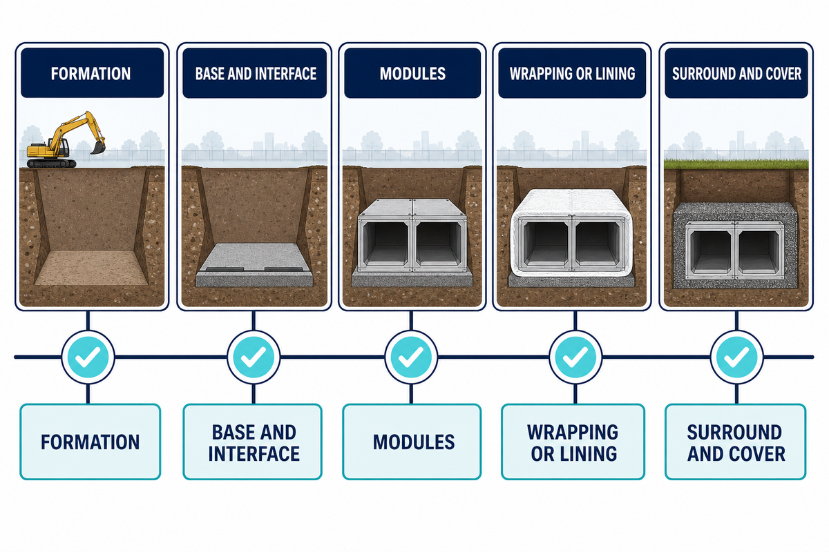
Installation is a sequenced process. For a parallel construction-coordination view, see Hydro International’s guidance. The excavation must be made and safety and temporary works measures need to be installed. Release the formation, and proceed to install base and separation layers, inspect the interface, and then install the module arrangement. Protect the formation from damage and from vehicles, plant, and uncontrolled fill.
- Hold point 1, formation: measure level and moisture, check for soft spots and groundwater, utility impacts, and record the release decision.
- Hold point 2, base and interface: record the base layer and separation or drainage materials, line, level, and the approver.
- Hold point 3, modules: inspect the model and connections, check orientation and access, and assess pipe interfaces, and check for damage and quantity.
- Hold point 4, wrapping or lining: check for penetrations and assess repair before cover.
- Hold point 5, surround and cover: check the placement sequence, levels, protection, and method of compaction and final access.
The installation team needs to understand if a check is visual, requires a measurement, a test, or a design decision. Product handling and descriptions provided by the supplier doesn’t make the supplier the project installation contractor or the approving engineer. The responsibilities need to be clearly defined in the method statement.
When the parties agree to a third-party loading inspection, the inspection may assess appearance, dimensions, packing and the sealing and securing of the container and may document it with photographs. This inspection supports the record of supply. It doesn’t confirm the installation of an underground system, construct a substitute for local construction inspection, or verify a future hydraulic result.
Maintenance, Acceptance and Handover Records
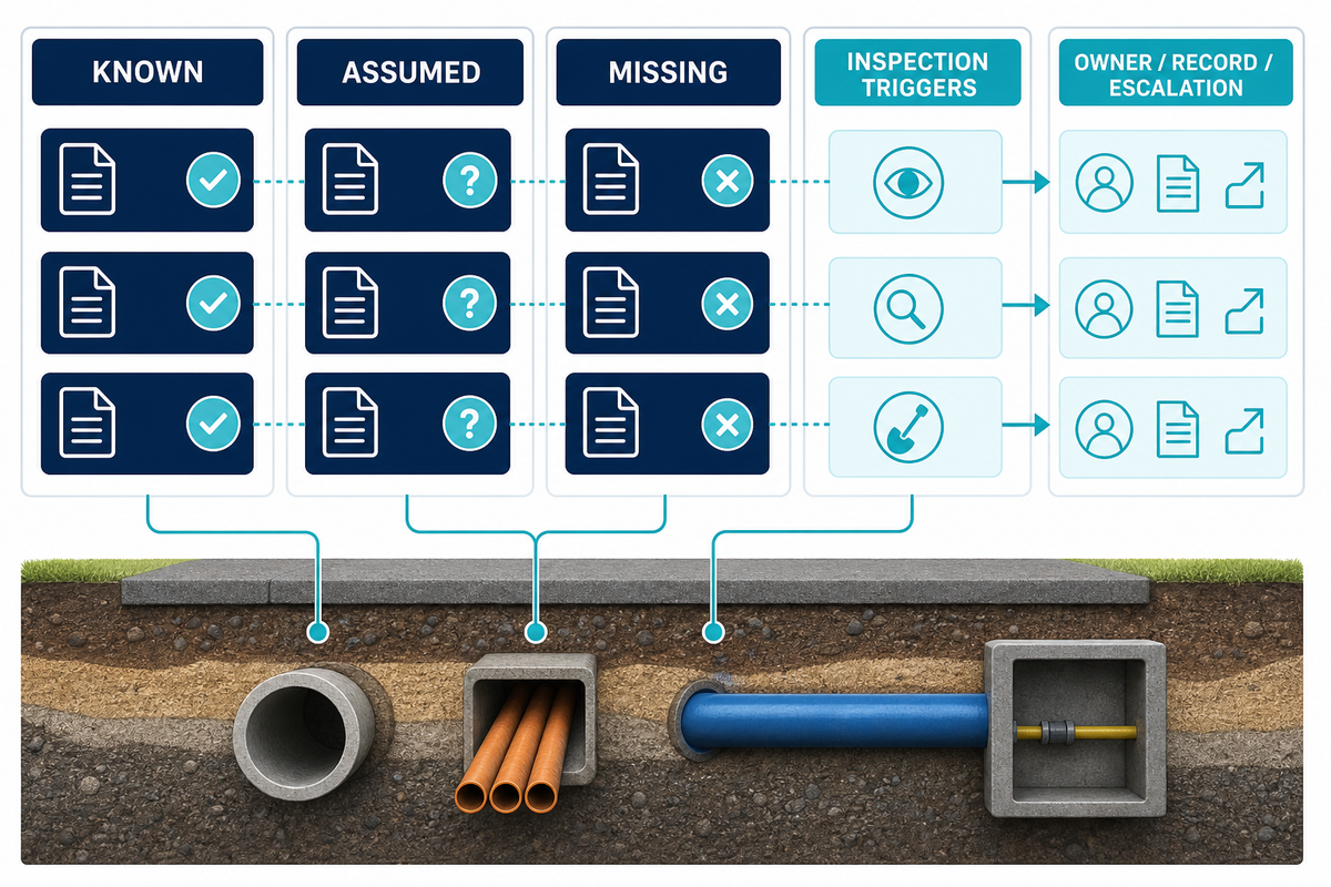
If a system is buried, the only part the owner can maintain is what’s accessible. SusDrain’s geocellular storage reference provides related inspection and maintenance context. For this reason, acceptance should include installed drawings along with inlet and outlet, pretreatment, overflow, access, and inspection information. The handover file should describe what’s visible, what isn’t accessible, what must be inspected and what the owner is obligated to respond to.
System Evidence Compass for handover
Known: there are as-built records, photographs, approved changes, test or commissioning notes, and the owner’s sign-off.
Assumed: a proposed responsibility or operating practice is pending confirmation.
Missing: until the document is supplied by the named owner, the item can’t be relied upon by the team.
A measurement register can carry example placeholders such as 12 m² for area, 800 mm for cover, 25 kPa for a recorded pressure, 6 L/s for an approved flow note, 20 °C for a test condition, 24 hr for an inspection window, 2 days for a response target, 2% for a stated sample, 12 months for a review reminder, 5 m for an access reach, 300 kg for a retained sample, 3 tons for a delivery note, 4 bar for a gauge observation, 50 kW for nearby equipment, 10 min for a hold point, 15 sec for a valve response, 1 year for a document review, 2 cm for an observed level difference, 4 kg/h for a process note, 8 MPa for a reported test condition, 100 psi for an instrument reading, 60 Hz for site power, 30 V for a control circuit, 10 A for a measured draw, and 5 W for a sensor. These are merely examples of traceability and are not proposed settings for geocellular stormwater modules nor intended for any project design.
Symptom-based inspection triggers include unexpected ponding, blockages to inlets, sedimentation, surcharge, odors, damaged access covers, settlement, and overflows. The first step in the inspection should focus on the symptom and the associated layer. Don’t think that then adding modules, raising a cover, or cleaning one inlet will remedy the problem if the root cause is yet undiscovered.
Limit a maintenance period to a given interval only if the project authority and manufacturer define such a requirement. A maintenance plan can define numerous elements (the trigger, method, access, safety, waste, owner, record, and escalation) without stating a maintenance interval. Likewise, substantiating a service life or payback claim requires project specifics; they can’t be generalized based on the name of a module.
How to Prepare a Supplier Brief
A concise vendor brief will avoid generic quotes. The project-information emphasis follows the coordination principles in Hydro International’s design paper. Provide the project details and delivery location, but keep the customer and distributor names confidential unless publication is approved. Indicate the preferred route, the area or catchment, the hydraulic and structural duties, the lid and outlet concepts, the wrapping or lining boundary, and the required documents.
- Project status, desired delivery time frame, preference for containerized or bulk shipments, and a contact person.
- Soils and groundwater data, site plan, and details of the local authority.
- Evidence for the objective to provide detention, attenuation, or infiltration and for the treatment and reuse of water.
- Pipe and structural interfaces and covers, access and pipe interfaces, and pipe and structural constraints and inspection points.
- Only enter model or load grade where the designer has already selected it, other options required.
- Document list: product data, order-specific inspection status, packing record, certificates or reports as available, and loading photos (if necessary).
The brief should focus on what’s still to be confirmed. For instance, confirm if the requested report is for the specific model and materials being used, if a test is internal or external, if the accessories are included, and if a supporting geotextile, geomembrane, or EPDM is purchased through the supply/manufacturing process, rather than being made on the core injection-moulding line. This is more useful than a general “send all certificates” request.
AQUA Rain Water can arrange the selection and batch inspection of the product, export packing, loading supervision, provision of related documents, and offer remote support and technical advice for the product. The current factory record states that the operation was established in 2009, has approximately 15 years of export experience, uses 30 injection-moulding machines in two shifts, and has owner-confirmed core moulded-module capacity of approximately 1,000 m³ per day with annual export volume around 300,000 m³. The owner confirmed the core moulded modules have the capacity of approximately 1,000 m³ per day, and over 300,000 m³ of export is done annually. The actual time will depend on the model, the preparation of the materials, the order mix, and the season. Planning figures in the supplied factory record are not delivery promises: the operation runs two shifts over 24 hours; one 40HQ of core modules is described as approximately 2–3 days, or up to about 7 days excluding raw-material preparation; a normal factory audit generally takes 1–2 days; and loading supervision generally takes 1 day, or 2 days depending on the loading schedule. Confirm the model, material preparation, order mix, season and appointment before using any of these figures. Core capacity remains approximately 1,000 m³ per day, and annual export volume is around 300,000 m³ per year in the supplied record.
AQUA Factory and Quality Boundaries
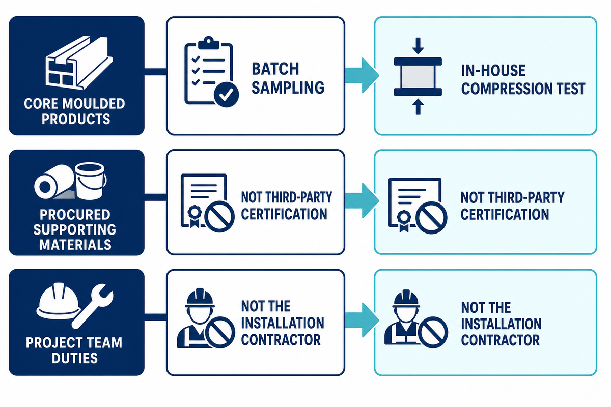
The supplied factory record describes an approximately 2% batch sampling workflow for dimensions, color, appearance, and compression with an in-house compression test. For the separate project-design and inspection context, see Hydro International’s geocellular design guidance. Customers have the option to arrange factory witnessed testing and/or receive a test video. This is an owner-confirmed internal process description, not third-party certification, a statistically defined acceptance plan, or proof that every project will receive the same report package.
The same boundary applies to supporting materials. Geotextile and geomembrane, and the EPDM pond liner, which were procured, were coordinated through AQUA’s supply process. At this time, it shouldn’t be mentioned that all products in this wider range are manufactured on the injection-moulding lines. Likewise, the sampling and compression workflow for moulded products can’t be automatically extended to all procured products.
AQUA supplies products, supporting materials, product-related documents, remote guidance, loading supervision, and technical support for the ordered products. AQUA doesn’t act as the project installation contractor; thus the customer, or the project team appointed by the customer, is responsible for the approval of the design and construction of the system and for ensuring safe access, compliance with regulations, as well as for the operation of the system. Whether the system is a storage tank along a road, part of a flood protection system, or associated with a climate change allowance, ensure that flow control and acceptance remain clear. Assume high density polyethylene (HDPE) or another material only if the data sheet for the order confirms it.
Geocellular Stormwater Modules FAQs
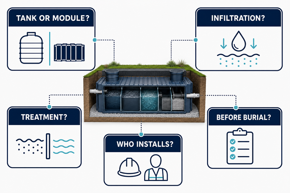
Are geocellular stormwater modules the same as a stormwater tank?
Read the practical answer
They can be used as the storage body of an underground geocellular stormwater tank or attenuation system, but the terms don’t define the complete assembly. A geocellular tank is therefore a system description, not a complete approval. SusDrain’s geocellular storage guidance describes the same need to separate the storage body from its interfaces. A tank arrangement also includes the surrounding material, inlet and outlet controls, access, overflow, inspection, structural assumptions, and the local approval route. Confirm the duty and interfaces before treating two product names as interchangeable. For example, a lined detention tank beside a road may need a different outlet, access detail, and inspection record from an infiltration trench under a landscaped area, even if both are described as modular storage. The specification should identify which component stores water, which controls discharge, which provides treatment, and which party accepts each interface before cover-up.
Can modules be used for infiltration or soakaway?
Read the practical answer
Potentially, where soil, groundwater, pollution risk, structural conditions, and local requirements support that route on the specific project. Infiltration isn’t established by a catalogue label or a nominal void description. The project team should provide infiltration evidence, define pretreatment, confirm separation requirements, and state how performance and maintenance will be checked.
Do geocellular modules treat stormwater?
Read the practical answer
Not automatically. Modules primarily provide a storage structure; treatment and sediment control normally require separate components and maintenance responsibilities. A specification should identify the water-quality objective, the treatment train, the inspection access, and the owner for cleaning or disposal. Avoid calling stored water treated without a defined treatment process and evidence.
What should be checked before a system is buried?
Read the practical answer
Check the released formation and base, module model and orientation, connections, access openings, inlet and outlet interfaces, wrapping or lining continuity, protection, photographs, levels, and responsible approvers. Record any deviation before cover-up. The final handover should connect these records to the as-built drawing and the owner’s inspection plan.
Does AQUA install the complete underground system?
Read the practical answer
AQUA supplies products, supporting materials, documents, remote guidance, loading supervision, and product-related technical support that can be arranged. AQUA doesn’t present itself as the project installation contractor or undertake full installation construction. The appointed designer and contractor remain responsible for the approved design, construction method, site safety, local requirements, and acceptance.
When to Move from a Guide to a Project Review
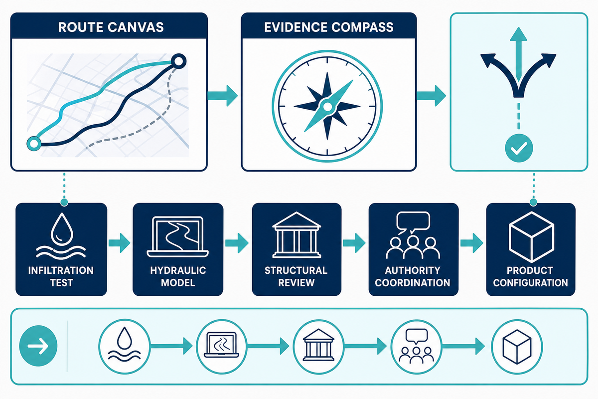
When the route canvas indicates a preferred outcome and the evidence compass shows the remaining unknowns, move to project review. The subsurface stormwater management systems overview is a useful related route reference before the product page is used for configuration.
Before that review, compare the open items with King County’s surface-water design manual as one example of a current jurisdictional reference. The next step is probably not a purchase order. It may be an infiltration test, a hydraulic model, a structural review, a pretreatment decision, an access detail, or a coordination meeting with the approving authority.
Please send the project brief along with any drawings or markups, inflow/catchment data, levels, notes on soil and groundwater, assumptions for loading and cover, the location of inlets and outlets, access, and delivery requirements, as well as the documents you’ll need for review. While working on the configuration and quote for the product, please follow the product page guide outlined.
Discuss your stormwater module project brief
References & Sources: Evidence Notes
This guide references the following sources for some preliminary design limits. They shouldn’t be used as a substitute for the standard, approval manual, engineering calculations, or the inspection plan for a particular design.
- For storage and infiltration limits along with a consideration for treatment and an inspection and maintenance context, see SusDrain, Geocellular storage systems.
- For design risk and construction coordination, see Hydro International, Tips for trouble-free geocellular design.
- As a possible reason for the need to check the regional changes to current jurisdictional standards, the following reference the King County Surface Water Design Manual:
- For the boundary between infiltration and groundwater protection, see U.S. EPA, Green infrastructure and groundwater protection.
The restricted factory records used in the limited statements made in this article apply only to the current factory records. Order and project-specific requirements and limits for configuration, testing, packing, delivery, and supporting documents remain project-specific and may vary.
About the author

Grayden Du
Export Director · AQUA RainWater Solutions
Grayden Du is Export Director at AQUA RainWater Solutions. His work spans geocellular detention systems, underground stormwater storage and subsurface water management. Drawing on more than 16 years of hands-on experience across over 30 country markets, he explains technical principles, system choices and practical project requirements.
About AQUA RainWater Solutions
AQUA RainWater Solutions manufactures geocellular stormwater modules, shallow attenuation systems and ground-reinforcement grids, and coordinates the supply of geomembranes, geotextiles and EPDM pond liners. We help match system interfaces and specifications, with batch inspection for moulded products, product documentation and export-delivery support.

![Ground Grid Applications & Ground Reinforcement [Guide]](https://aquarainwater.com/wp-content/uploads/2026/09/ground-grid-applications-ground-reinforcement-blog-featured-768x512.png)