Get in touch with AQUA Company

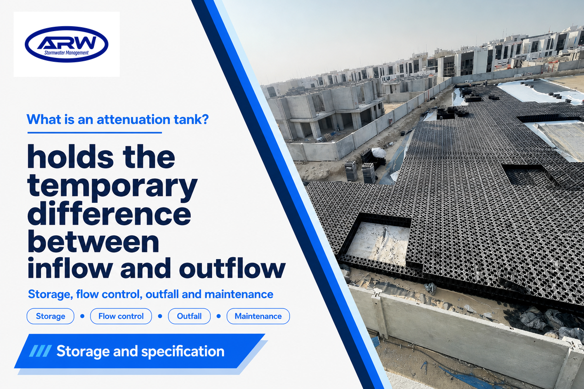
A stormwater attenuation tank allows a drainage system to store stormwater runoff temporarily and releases it gradually. As a buyer, the important difference for you is between the storage product and the complete working system. The evidence for crates, lining, flow control, outfall and maintenance access is different.
Buying or specifying a tank? Start with the approved drainage duty, then translate it into a complete product configuration and quotation. The worked examples below explain published storage figures; they do not size a site or approve an installation.
This guide focuses on the technical specification and handover of attenuation tanks. For other considerations, please see the existing attenuation tank purpose and applications guide.
What is an attenuation tank?
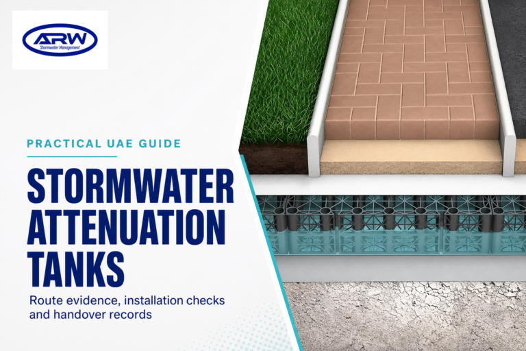
An attenuation tank is a storage feature of a stormwater drainage system which slows the release of runoff. During a rainfall event, runoff may flow to the tank faster than it can drain from the outlet. The system is designed to store the runoff until it can be slowly discharged to the downstream drainage system.
The English national sustainable drainage standards say attenuation storage is achieved when the controlled outflow is less than the inflow. An underground storage tank can preserve surface land for other uses, but its presence alone doesn’t improve water quality or guarantee that it will prevent flooding.
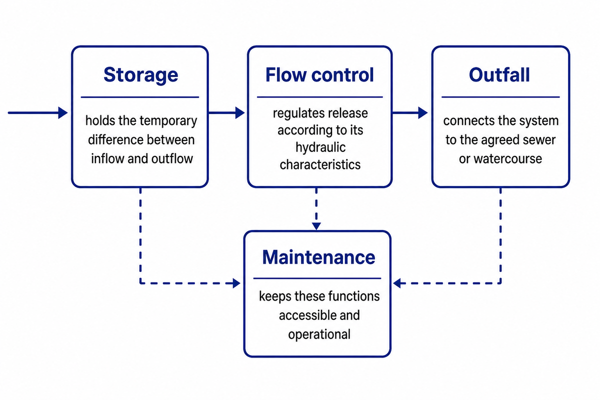
- Storage: holds the temporary difference between inflow and outflow.
- Flow control: regulates release according to its hydraulic characteristics.
- Outfall: connects the system to the agreed sewer or watercourse.
- Maintenance: keeps these functions accessible and operational.
A quotation which only provides a module addresses the first function of the system. Find out who will provide and verify the others before treating this as a complete attenuation system.
How an attenuation system manages stormwater
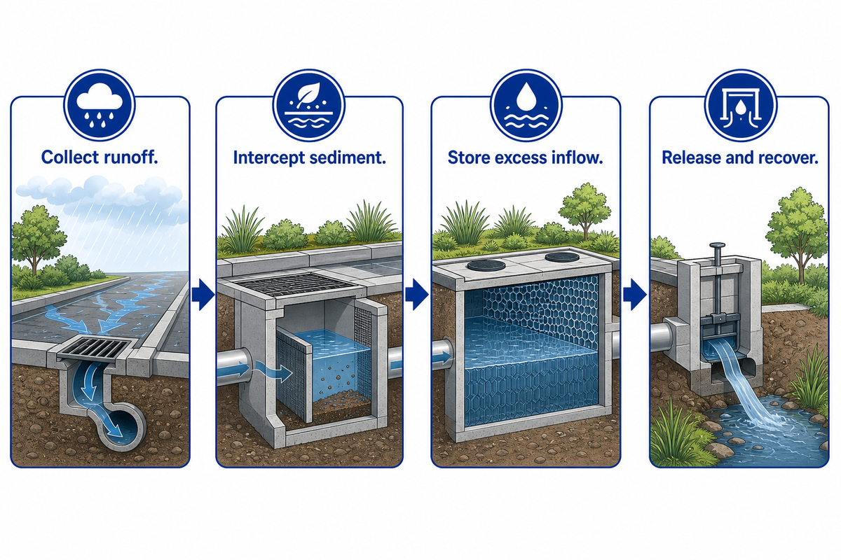
The release of water from an attenuation system is dependent on many factors, i.e. water levels in the tank, the type of control being used, and the conditions of the outlet. Water flow depends on water levels, the control device and conditions downstream; water is released according to those hydraulic conditions, rather than at a universally constant rate.
How does an attenuation tank work?
- Collect runoff. Convey stormwater runoff and surface water from the designed catchment.
- Intercept sediment. Apply the specified pretreatment before the storage zone.
- Store excess inflow. Fill the available tank volume during the storm.
- Release and recover. Discharge through the outlet and recover capacity before subsequent rainfall.
Orifices, weirs and vortex controls are different from one another. A blocked outlet or surcharged sewer can alter the intended behavior of a control; therefore a designer must assess what happens in the absence of the intended behavior and the level of the receiving water, and not just the volume of the crate.
The US Army Corps of Engineers reservoir-modeling guidance explains that detention changes the timing of the runoff hydrograph. Delayed releases can coincide with other downstream flows: reducing a site’s peak discharge doesn’t, by itself, illustrate that a reduction in the risk of flooding has occurred downstream.
Use the detailed attenuation tank flow and outlet explanation alongside the project calculations rather than using a basic diagram as a construction design.
Attenuation, soakaway and rainwater harvesting: separate functions
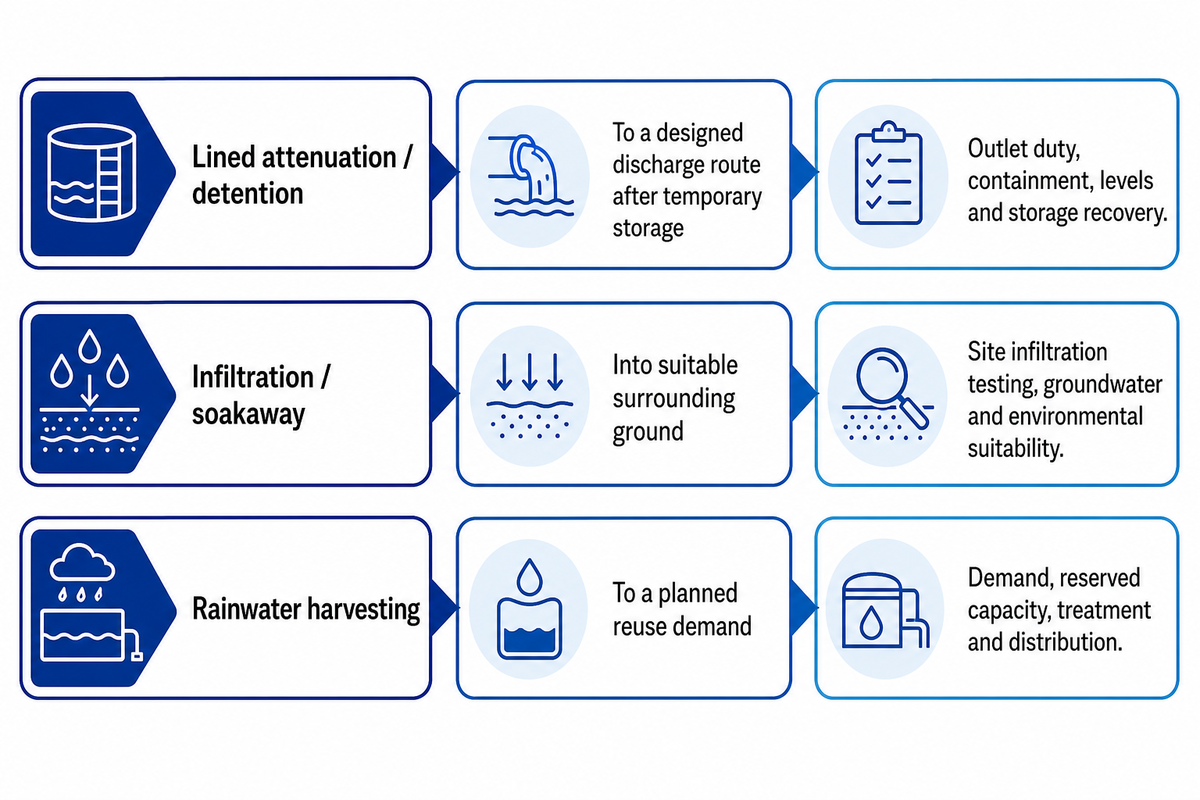
Storage of runoff can be done via attenuation and soakaway, and runoff can be harvested and stored for re-use. A combined system must demonstrate each intended function instead of counting the same storage space twice.
| Function | Where water goes | Critical evidence |
|---|---|---|
| Lined attenuation / detention | To a designed discharge route after temporary storage | Outlet duty, containment, levels and storage recovery. |
| Infiltration / soakaway | Into suitable surrounding ground | Site infiltration testing, groundwater and environmental suitability. |
| Rainwater harvesting | To a planned reuse demand | Demand, reserved capacity, treatment and distribution. |
CIRIA’s susdrain geocellular storage guidance describes both storage and soakaway configurations. An unlined system relies on infiltration if the soil and surrounding conditions are acceptable. An assessment of groundwater and an acceptable outfall are still required for a lined tank where infiltration is poor.
The US Department of Energy rainwater harvesting review considers captured water as a supply to be treated and distributed later. Rainwater harvesting systems may contain water during a storm. Thus, reuse water already occupying the system volume can’t automatically be credited as empty attenuation capacity.
Capacity check: England’s standard 2 specifically rejects assuming that garden-use water butts guarantee available storage. For shared reuse and attenuation, ask the designer to show how the reserved storage remains available.
The soakaway crate drainage guide provides an alternative configuration for ground-discharge projects. Choose the function before choosing the wrap.
Which tank construction fits the site?
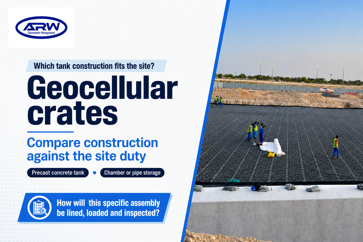
The hydraulic duty, site constraints and maintenance method should be considered when choosing the tank construction. Geocellular crates, precast tanks and chamber or pipe systems provide different options; suitability depends on the total installed configuration rather than a preference for one material.
| Construction | Useful characteristic | Question before selection |
|---|---|---|
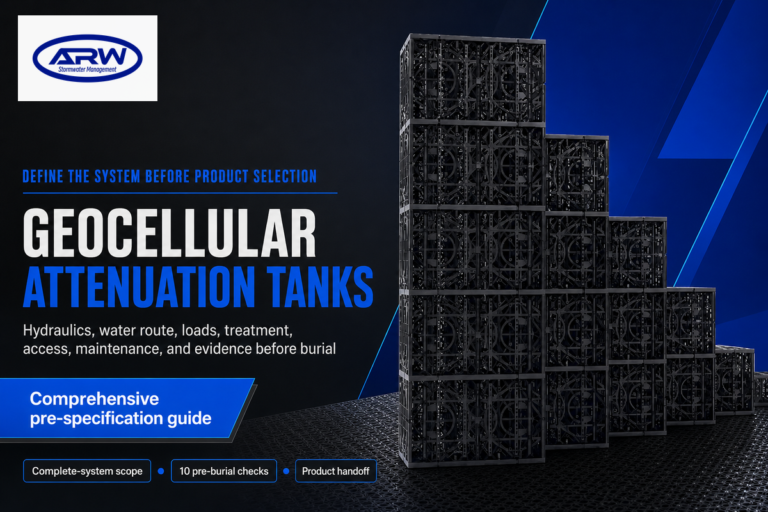
| Geocellular crates | Modular assembly with high void storage | How will this specific assembly be lined, loaded and inspected? |
| Precast concrete tank | Defined structural modules and access openings | What handling, joints, support and groundwater checks are included? |
| Chamber or pipe storage | Storage arranged through chamber/pipe geometry | Which volume and maintenance routes are demonstrated for the assembled system? |
CIRIA describes modular systems for underground applications, including trafficked areas where structural performance is demonstrated. A high-performance product description isn’t a substitute for evidence covering the actual arrangement and load case.
A 2014 vendor-reported Quantico precast project used 16 modules and four manways, together with a liner and outlet. Those details belong to the named Oldcastle project, not to AQUA; their useful lesson is that access and containment are part of the assembled solution, rather than optional details discovered after burial.
When comparing different alternatives, consider how the Contractor will construct and inspect the system efficiently, within the confines of the excavation and working space. A modular design that shows how the components fit together in a drawing doesn’t necessarily show a feasible installation and maintenance route.
Reading an attenuation tank storage specification
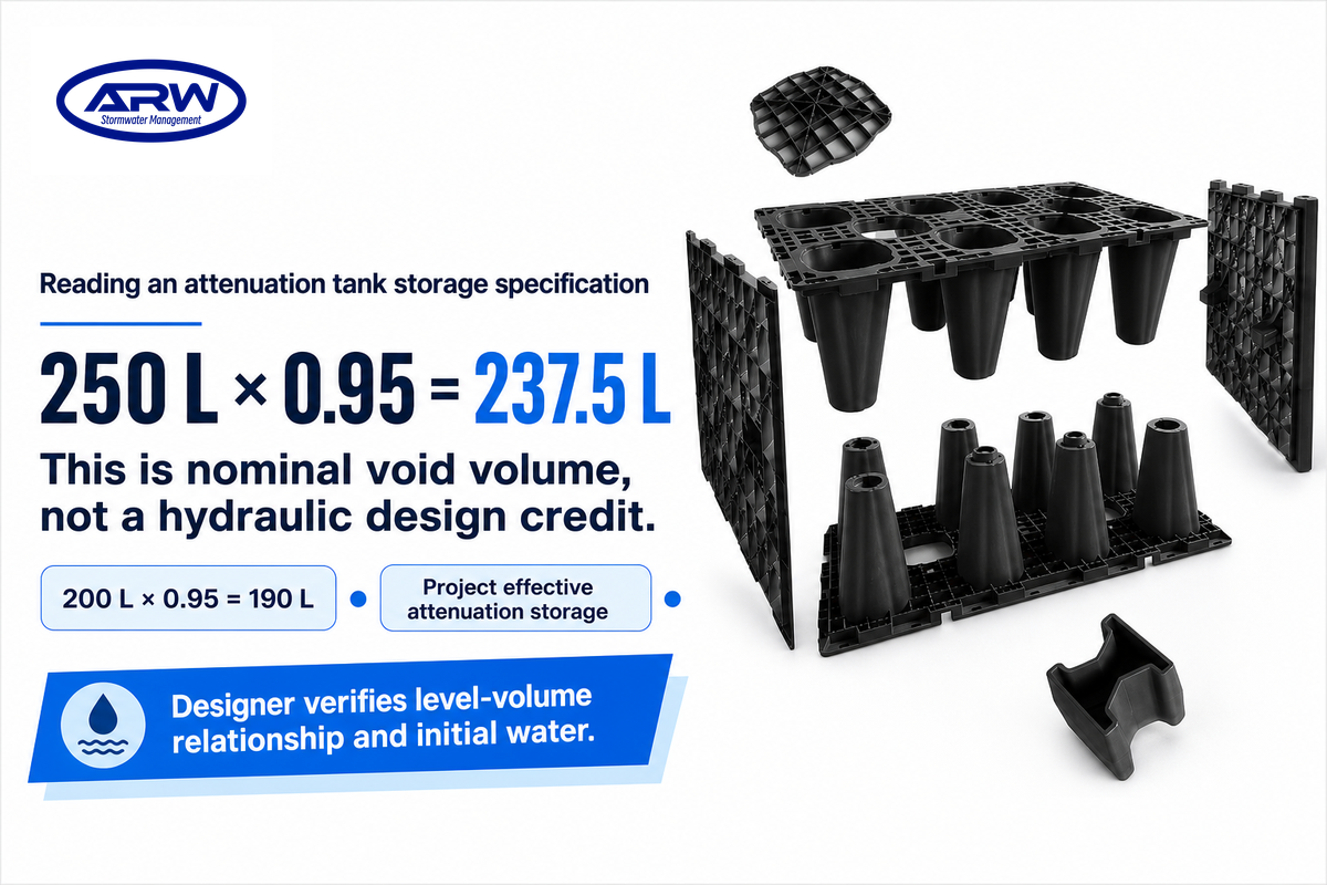
An attenuation tank specification should distinguish between geometric volume, nominal water storage volume and project-credited storage. AQUA’s published ARW1050 configurations provide a useful arithmetic example, but their calculated void volumes don’t establish the water level range, starting conditions or hydraulic capacity that a drainage designer can credit to a particular site.
Storage Specification Translation Table
| Item | Published value or definition | What the buyer must establish |
|---|---|---|
| 500 mm complete ARW1050 assembly | 1,000 mm × 500 mm × 500 mm | Confirm complete assembly, revision and included parts. |
| Its geometric envelope | 0.250 m³ = 250 L | Outer volume includes plastic; it is not empty water space. |
| Its published void ratio | 95% | AQUA-specific figure; do not apply across all products. |
| Its calculated nominal void storage | 250 L × 0.95 = 237.5 L | Check whether a quoted capacity already includes porosity. |
| 400 mm complete ARW1050 assembly | 1,000 mm × 500 mm × 400 mm | Confirm the shorter complete configuration. |
| Its geometric envelope | 0.200 m³ = 200 L | Use the dimensions of the ordered assembly. |
| Its calculated nominal void storage | 200 L × 0.95 = 190 L | This is nominal void volume, not a hydraulic design credit. |
| Project effective attenuation storage | Storage available over the adopted design levels | Designer verifies level-volume relationship and initial water. |
| Strength and installed loading | Product test value versus project load case | Long-term behaviour, assembly, cover and groundwater need separate evidence. |
According to AQUA’s configuration data, the complete units use a 95% void ratio. These specifications are for the stated models and assemblies, and aren’t independent tests or a value to assume for a different crate.
Consider a potential client reviewing a 500 mm complete assembly against a 400 mm assembly. For the first unit, 1.0 m × 0.5 m × 0.5 m = 0.250 m³ (250 L) of exterior envelope; with the published 95% void ratio, this gives 237.5 L of nominal water space. The shorter unit gives 0.200 m³ (200 L) and therefore 190 L using the published ratio. The quotation may already state 237.5 L as void storage; multiplying this number by 0.95 once more applies porosity twice. The potential client must first interpret the meaning of the quoted litre figure and then ask the drainage designer which storage is actually available between the adopted levels. Neither adjustment determines the size of the geocellular attenuation tank.
The public scope of BS EN 17152-1:2019 separates box characteristics and docs for assembly into a complete system. Reviewing that scope does not establish AQUA conformity. Request the relevant model-specific product docs and assess the AQUA geocellular tank dimensions and configs against the proposed assembly.
What a project-specific drainage design must establish
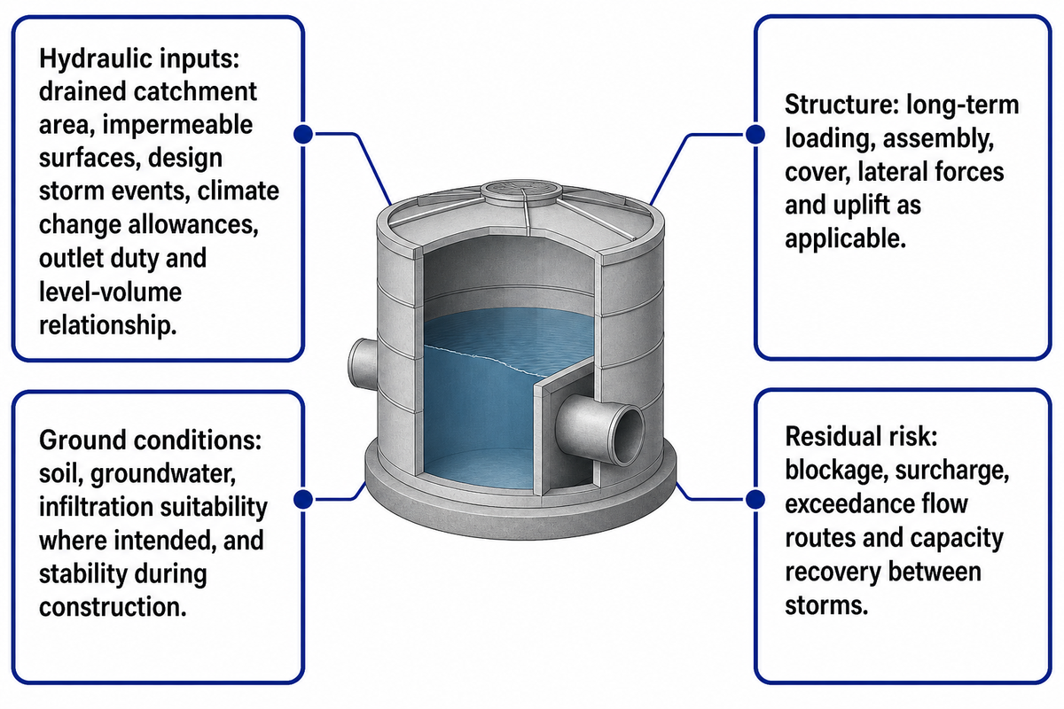
A project-specific drainage design must establish inflow, discharge, available storage, installed structural conditions and failure behaviour. The engineer needs catchment and rainfall data, levels, and ground investigations, and the receiving route. Supplier dimensions and compression test values don’t replace hydraulic calculations for the drainage works and infrastructure, ground investigations, and structural assessments for the attenuation tank installation.
“In determining the maximum water levels, flows and attenuation storage volumes, the critical duration rainfall event should be used.”
- Hydraulic inputs: drained catchment area, impermeable surfaces, design storm events, climate change allowances, outlet duty and level-volume relationship.
- Ground conditions: soil, groundwater, infiltration suitability where intended, and stability during construction.
- Structure: long-term loading, assembly, cover, lateral forces and uplift as applicable.
- Residual risk: blockage, surcharge, exceedance flow routes and capacity recovery between storms.
Consider a residential situation where the calculated runoff volume equals the nominal storage of the tank, but the receiving sewer is already full during heavy rainfall. The outlet may then discharge less water than the empty-start calculation assumed. Water may remain in the tank when the next storm event arrives. Increasing the module count without checking the outfall can leave the underlying constraint in the design unresolved. The design team should assess the downstream condition, the recovery period and the path taken by excess rainwater. The contractor should then be provided the matching construction details. This is a hypothetical design constraint, and not a reported AQUA installation.
Leeds City Council’s local drainage criteria demonstrate that receiving river levels and repeat-storm capacity should be considered, illustrating why local authority requirements must be assessed separately. Event-based sizing of tanks can’t be replaced with the annual amount of rainfall or number of days of rain. Short-term ultimate compression values don’t state what vehicle load an installed system can accept.
Inspection, cleaning and failure routes
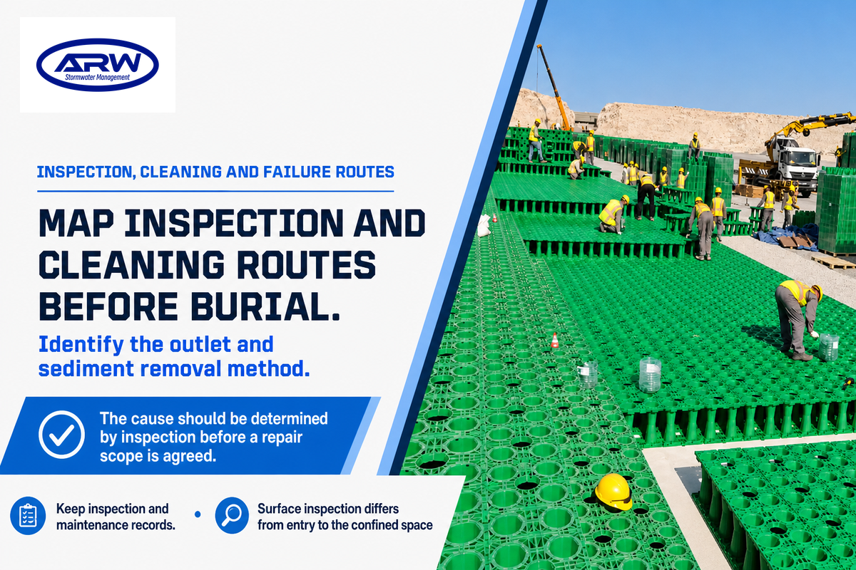
Attenuation tanks require reachable inspection points and maintenance to remove sediment and debris; the outlet and containment should be checked. An operating plan should state what tasks should be performed, and at what intervals, by whom; a storage product can’t remain reliable if maintenance equipment can’t reach the locations where material has accumulated.
Do attenuation tanks need maintenance?
Yes. CIRIA recommends maintaining upstream silt traps, manholes and pipes, to prevent sediment from building up, blocking the flow control and eventually consuming the available storage. Pretreatment helps protect the tank but a sediment trap isn’t adequate treatment for every pollutant or discharge destination.
Do
- Map inspection and cleaning routes before burial.
- Identify the outlet and sediment removal method.
- Keep inspection and maintenance records.
Don’t
- Assume a manhole permits safe personnel entry.
- Adopt a universal cleaning interval without site evidence.
- Treat clear water at one inspection as proof of full capacity.
Reduced discharge may be due to blockage of outlet, surcharge downstream, or some other fault; a leak may mean a loss of containment or a connection. The cause should be determined by inspection before a repair scope is agreed. Emergency overflows and exceedance routes should be planned in the normal course of design; they shouldn’t be improvised during a failure involving sudden surges.
The Health and Safety Executive’s confined space guidance advises avoiding such work where possible and assessing and controlling the particular risks where it’s unavoidable. Surface inspection differs from entry to the confined space; entry requires a safe method, isolation and emergency arrangements. They must be arranged by a competent person.
England Standard 7 addresses the management, safe access and sediment removal. An interim operator should be identified before adoption, together with a funded long-term owner. Support from the manufacturer doesn’t transfer responsibility for operation.
Current sustainable drainage requirements: an England example
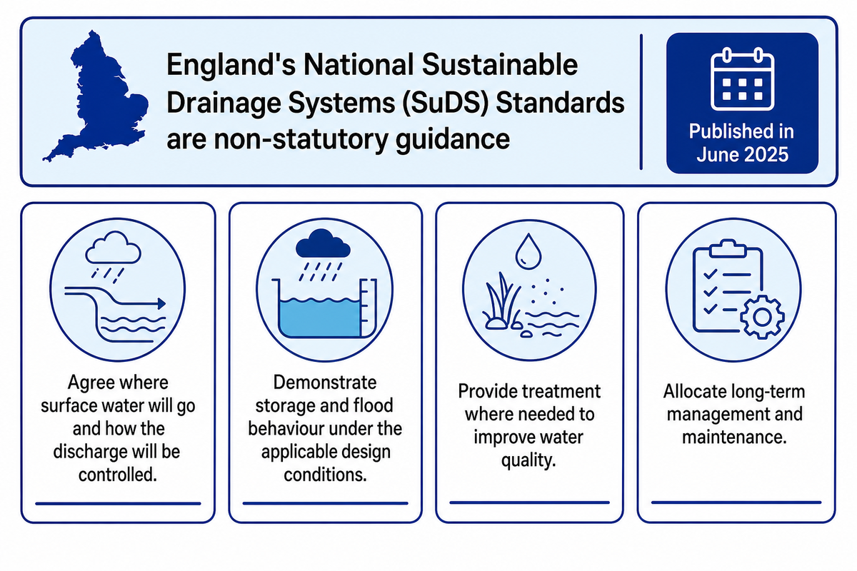
England’s National Sustainable Drainage Systems (SuDS) Standards are non-statutory guidance for integrating sustainable drainage in development. Published in June 2025, they address much more than tank volume, including runoff destinations, flood risk, water quality, amenity, biodiversity and long-term management; they aren’t a rule requiring a particular tank on every UK site.
As shown in the government publication record, the publication date is given as 19 June 2025, with an update given on 30 July 2025. For a project being specified now, it’s recommended to check the applicable authority and current guidance, and determine the requirements for consent or adoption, prior to specifying a storage configuration.
- Agree where surface water will go and how the discharge will be controlled.
- Demonstrate storage and flood behaviour under the applicable design conditions.
- Provide treatment where needed to improve water quality.
- Allocate long-term management and maintenance.
Underground tanks can be included in a sustainable drainage system, but on their own don’t satisfy all aspects of sustainable development. A more complete approach may be needed to address the local environment, sustainability and resilience, especially in urban areas.
Tanks can’t be used to replace wastewater treatment plants, and a product label shouldn’t be assumed to state that the system or design as a whole will be in compliance. Water management systems should be designed to comply with a project’s sustainable water management strategy and the approval route.
From technical specification to a comparable supplier quote
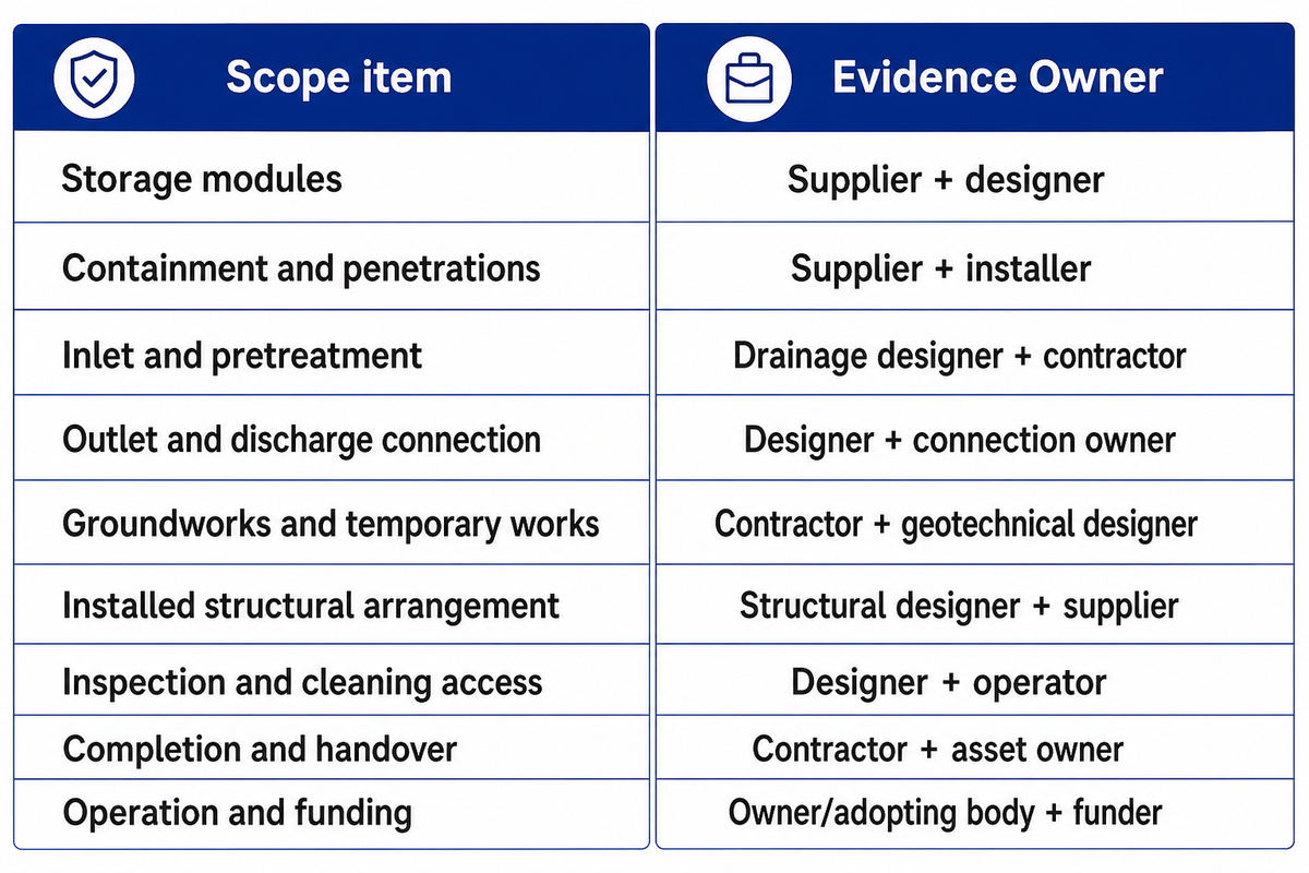
Attenuation tank quotations require the same storage requirements, installed scope boundaries, and evidence in every quote. Distinguish between the supplier’s product and the work for engineering, civil, outlet works, and operation, then identify who owns the interfaces. A lower module price may exclude work that the customer is still obliged to buy.
The Cabinet Office’s public procurement guidance on technical specifications covers performance, safety, dimensions, evidence and whole-lifecycle considerations. The table below uses those considerations to create an author-made purchasing method; this isn’t a tested savings claim or universal contract template.
Attenuation Quote Scope Reconciliation
| Scope item | Evidence owner | Require in each offer | Consequence of a gap |
|---|---|---|---|
| Storage modules | Supplier + designer | Model, complete parts, quantity and credited volume | A cheaper module count may provide a different storage duty. |
| Containment and penetrations | Supplier + installer | Liner, protection, joint/penetration details; priced inclusions | Water-retaining scope can sit outside the crate price. |
| Inlet and pretreatment | Drainage designer + contractor | Sediment/treatment duties and supplied components | Storage can receive sediment without a maintainable removal route. |
| Outlet and discharge connection | Designer + connection owner | Control duty, levels, connection consent and responsible installer | Tank supply alone leaves no agreed discharge system. |
| Groundworks and temporary works | Contractor + geotechnical designer | Excavation, dewatering, bedding and disposal boundaries | Civil work exclusions can exceed the apparent material saving. |
| Installed structural arrangement | Structural designer + supplier | Load cases, cover, long-term evidence and assembly drawings | A compression grade can be mistaken for site approval. |
| Inspection and cleaning access | Designer + operator | Ports, chambers, equipment reach and safe method | Buried assets may be inaccessible to planned maintenance. |
| Completion and handover | Contractor + asset owner | As-built drawings, checks, records and acceptance criteria | Installation completion does not demonstrate operational readiness. |
| Operation and funding | Owner/adopting body + funder | Interim and permanent operator, funding and responsibility dates | A maintenance plan may lack an accountable, funded operator. |
Let’s assume one quotation contains only crates, while the other contains crates and linings and outlet works. The customer can’t compare their totals until the contractors identify which omitted items are in the civil works package, the designer confirms compatible interfaces, and finance includes the remaining cost commitments. There may be real savings after that comparison. The apparent price gap may disappear. The operator needs a funded cleaning method and records at handover rather than a manufacturer’s general maintenance statement. Record all inclusions and exclusions against the same drawings and storage definition, ask the named party to accept responsibility, and compare the combined scope. This hypothetical comparison shows how to assess a quotation without inventing an installed price per cubic meter.
An actual Derry City and Strabane District Council above-ground tank tender bundled design, supply and installation, with steel support, flooring and maintenance fall protection. Its scope highlights the importance of supporting works; this isn’t a benchmark for a sub-surface geocellular system.
AQUA’s manufacturing and supply scope differentiates moulded products from coordinated procurement of associated lining material; installation is by the appointed contractor. Match documentation to the ordered product model, material, and configuration. For assembly and handover, see the geocellular stormwater module selection and handover guide.
Key takeaway
AQUA’s 500 mm ARW1050 assembly has published calculated void storage of 237.5 L; the project designer separately verifies credited storage and the complete installed duty.
Send project drawings, required storage definition and relevant load conditions to AQUA to discuss a product configuration and price.
Discuss your geocellular tank specification
Frequently asked questions
Are attenuation tanks required?
A tank is one possible storage solution, not a universal requirement.
Read the design and approval considerations
The need for attenuation depends on the drainage strategy, site runoff and permitted discharge. Local planning, connection and adoption requirements determine what evidence is needed. An above-ground feature or another storage arrangement may provide the required function. England’s 2025 standards are non-statutory guidance and shouldn’t be read as a mandate to install tanks on every property. Confirm the proposed solution with the project designer and applicable authority.
How deep are attenuation tanks?
Installation depth is project-specific.
Read what determines the depth
Tank height and installation depth are different measurements. The drainage levels, available hydraulic head, cover, loading, groundwater and maintenance arrangement affect where a tank can be placed. AQUA’s published 400 mm and 500 mm complete-unit heights describe product configurations; neither figure gives an excavation depth or a safe cover requirement. Request the installed section drawing and structural assessment for the proposed layout instead of adopting a generic depth from another project.
How close can an attenuation tank be to a building?
There’s no universal setback established by this guide.
Read the site-specific checks
The relevant assessment depends on whether the system retains water or infiltrates it, foundation conditions, excavation effects, groundwater and local requirements. A distance intended for a soakaway shouldn’t be transferred automatically to a lined attenuation tank. Ask the geotechnical and drainage designers to assess the proposed location and construction method, and show the agreed separation on the drawings. Product dimensions alone can’t establish a safe position beside a building.
Can an attenuation tank be repaired?
Some faults can be repaired, but access and the cause determine the scope.
Read the repair boundary
Inspect the outlet, connections, containment and structure as appropriate. Clearing a blockage, repairing a liner and replacing a damaged buried module are different operations; assess feasibility and safe access before committing to a repair.
What size attenuation tank do I need?
The required storage comes from a project-specific hydraulic design.
Read how to translate design storage into a product order
The designer uses the drained catchment, rainfall data and storm durations, runoff assumptions, climate allowances, receiving conditions and allowable discharge. Calculations also need the available level range and starting storage state. An annual rainfall total, roof area alone or a simple “litres per property” rule can’t establish the complete duty.
After the required effective storage is defined, the supplier and designer translate it into the specific assembled product volume and layout. Check whether the stated capacity is geometric envelope, nominal void space or hydraulic credited storage. AQUA’s 237.5 L and 190 L examples illustrate nominal model figures only. The ordered quantity must follow the approved layout, complete parts and verified installed conditions, rather than a calculation based solely on advertised capacity. Confirm access, containment and outlet scope before issuing the order.
How much does an attenuation tank cost?
A meaningful price requires a defined scope.
Read how to compare costs
Compare the same credited storage, modules, lining, outlet, groundworks, structural work, access and handover obligations. Material-only and installed quotations aren’t directly equivalent. Obtain project-specific offers; the worked volume examples don’t establish a price or predict whole-life savings.
References & Sources
- UK Government – National Standards for Sustainable Drainage Systems (2025)
- US Army Corps of Engineers – Reservoir Modeling
- CIRIA susdrain, Geocellular storage systems
- US Department of Energy – Rainwater Harvesting Systems Technology Review
- Water Online – Vendor reported Quantico National Cemetery Detention Project (2014)
- British Standards Institution, BS EN 17152-1:2019, public scope
- Leeds City Council – Minimum development control standards for flood risk
- Health and Safety Executive – Introduction to working in confined spaces
- UK Government – National Standards Publication and Update Record
- Cabinet Office, Guidance: Technical Specifications
- eTendersNI – Derry City and Strabane District Council, T24-100CAP
Technical and procurement interpretation uses the public sources listed here. AQUA model data and supply scope are supplier-reported; hypothetical examples are illustrations, not completed client projects.

![Ground Grid Applications & Ground Reinforcement [Guide]](https://aquarainwater.com/wp-content/uploads/2026/09/ground-grid-applications-ground-reinforcement-blog-featured-150x150.png)