
Attenuation Tanks in the UK: 2026 Complete Guide for SuDS Approval
On paper, attenuation tanks are simple: a sealed underground volume that holds back stormwater and lets it out slowly. In the real world, they sit at the centre of planning approvals, LLFA comments, Part H requirements, and contractor risk. We see schemes pass first time because the drainage story is clear – and others bounce back repeatedly because the design doesn’t quite answer the questions regulators and asset owners are really asking.
This guide is written for UK developers, consultants, and contractors who need attenuation tanks that not only “work” in MicroDrainage, but also survive LLFA review, value engineering, and installation on a muddy, constrained site.
1. What Is an Attenuation Tank – in Practical Terms?
An attenuation tank is a sealed underground structure that temporarily stores surface water runoff during a storm and releases it at a restricted rate afterwards. Instead of sending all rainfall straight to the sewer or watercourse, the tank flattens the hydrograph: peak inflow is higher than outflow, so the difference is stored as volume in the tank.
In UK drainage strategies, attenuation tanks usually sit towards the bottom of the SuDS train – after source control and conveyance – and are sized to make the post-development discharge behave like the original greenfield site.
1.1 How an Attenuation Tank Works Day-to-Day
For a typical UK development:
- Rainwater runs off roofs, roads, and hardstanding into the site drainage network.
- Flows enter the attenuation tank through inlet pipework and manholes.
- During a design storm (for example, 1 in 30 or 1 in 100 year + climate change), inflow exceeds the permitted outflow for a period.
- The tank fills up to a safe operating level, holding back part of the volume.
- A flow control device (orifice plate or vortex control) throttles flows down to the agreed discharge rate.
- After the storm passes, the stored water drains down and the tank returns to empty or near-empty, ready for the next event.
Done properly, the downstream system “sees” a smooth, controlled discharge, not a violent peak.
1.2 Why Is an Attenuation Tank Needed?
In much of England and Wales, more than 5 million properties lie in areas at risk of flooding. Intensifying rainfall patterns and infill development mean most LLFAs now treat surface water as a major planning risk. Attenuation is needed when:
- The site cannot infiltrate enough water to ground to meet discharge limits safely.
- No suitable watercourse is available – or the receiving water body has limited capacity.
- The receiving sewer company caps your discharge at a low rate (for example, 3–5 L/s/ha).
- Downstream infrastructure was never sized for today’s hardstandings and climate allowances.
In short: attenuation tanks buy you time and volume where infiltration or open basins alone cannot solve the problem.
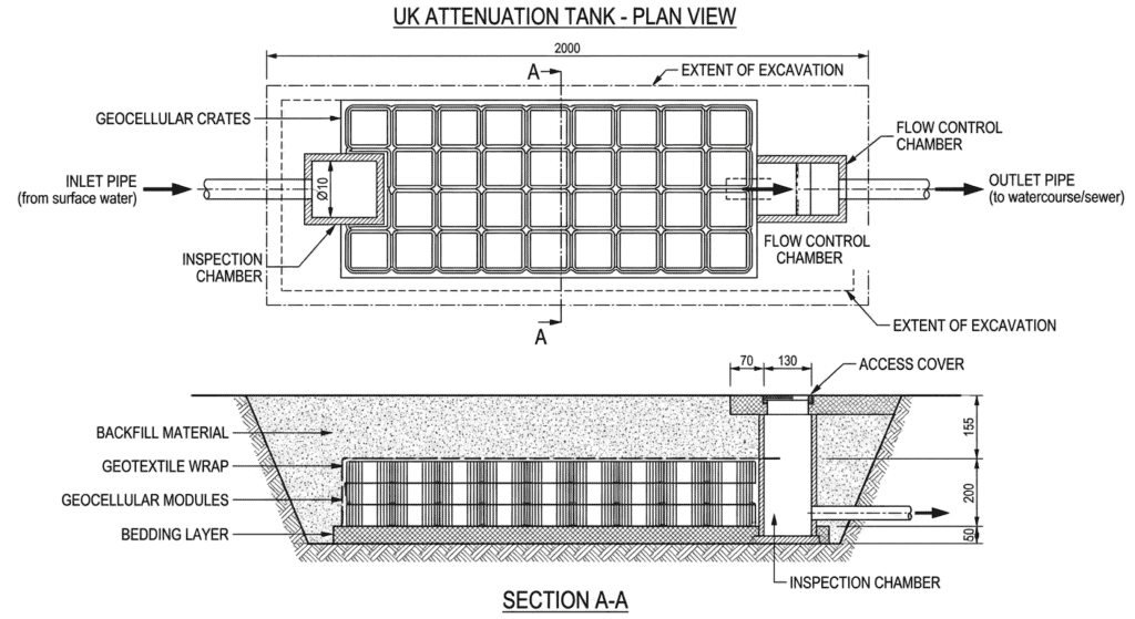
1.3 What Does an Attenuation Tank Actually Look Like?
On site, you rarely see the tank once it is finished – only manhole covers and inspection chambers. Beneath the surface, a modern attenuation system typically looks like:
- A rectangular block of geocellular crates, wrapped in a black geomembrane and geotextile, sitting in a clean, level excavation.
- Inlet and outlet pipes connecting to upstream drainage and downstream outfall chambers.
- Access points for jetting and CCTV, often via proprietary inspection chambers above the crates.
1.4 Key Benefits of Using an Attenuation Tank
- Planning compliance: Helps you hit greenfield runoff targets and satisfy SuDS hierarchy requirements when infiltration alone is not feasible.
- Land value: Keeps stormwater storage underground so you can use the surface for parking, play areas, or landscape.
- Predictable performance: Unlike marginal soakaways in clay, attenuation systems are not dependent on infiltration rates.
- Integration with SuDS train: Can work alongside permeable paving, raingardens, and swales as the “end-of-line” storage element.
2. Attenuation vs Infiltration: Choosing the Right Approach
Many UK projects still start with the wrong assumption – “we’ll just use a soakaway”. The reality is simpler if you separate the two concepts clearly:
| Aspect | Attenuation Tank | Soakaway / Infiltration System |
|---|---|---|
| Main function | Store and slowly release runoff to a sewer or watercourse | Soak water directly into the surrounding soil |
| Lining | Fully lined with impermeable geomembrane | Unlined or partially lined to allow infiltration |
| Soil dependency | Can be used on clays and low-permeability sites | Needs suitable infiltration rate (from BRE 365 test) |
| Regulatory emphasis | Managing peak flow and volume to greenfield rate | Proving no risk to structures or groundwater |
Rule of thumb: if your BRE 365 test shows poor infiltration or you are on a tight, urban site, an attenuation tank is usually the safer and more acceptable option. If you have clean, free-draining soils and space, infiltration can sit above or alongside attenuation in the SuDS train.
For a deeper comparison, see our dedicated article on attenuation tanks vs soakaways.
3. UK Regulatory Framework You Need to Satisfy
Most of the pain around attenuation tanks comes from missing one or two key regulatory requirements. The main documents you need to design against are:
3.1 National Planning Policy & SuDS Requirements
- National Planning Policy Framework (NPPF): latest revisions make SuDS the default for major developments, with surface water risk a material planning consideration.
- National Standards for SuDS: require systems to manage up to the 1 in 100 year + climate change event, with control of both peak flow and volume.
- Local LLFA guidance: often more restrictive than national minimums – many authorities require greenfield or better for discharge rates and specific allowances for climate change.
3.2 Building Regulations Part H3 (Drainage)
Part H3 sets out the disposal hierarchy for surface water:
- Infiltration to ground where practicable.
- Discharge to a watercourse.
- Discharge to a surface water sewer.
- Discharge to a combined sewer only as a last resort.
When you propose an attenuation tank that discharges to sewer or watercourse, you must show why infiltration is not feasible – usually by providing BRE 365 test results and a short assessment of local ground and groundwater conditions.
3.3 CIRIA SuDS Manual (C753)
The CIRIA SuDS Manual is not law, but in practice it is the technical reference your LLFA and water company expect you to follow. Your attenuation tank proposal should align with C753 in areas such as safety factors on volume, freeboard allowances, access for maintenance, and structural checks.
4. Main Technologies – With a Focus on Geocellular Tanks
In the UK, three technologies cover most attenuation schemes:
4.1 Geocellular (Modular Plastic) Tanks
Geocellular tanks use interlocking plastic modules to create a highly voided underground storage block. For many UK projects, they offer the best balance of excavation volume, build speed, and long-term performance.
- Typical void ratio: ~95% effective storage.
- Design life: 50 years or more when correctly specified and installed.
- Traffic loading: modules can be selected to suit car parks through to heavy goods vehicle areas (check manufacturer’s load tables).
- Flexibility: modular layout fits awkward footprints and shallow build-ups.
For most UK attenuation schemes on constrained sites, we find geocellular tanks deliver the lowest total installed cost once you include excavation, muck-away, and programme risk.
See our geocellular tank range for typical module sizes, load classes, and design support.
4.2 Precast Concrete Tanks
Concrete tanks still make sense for very high load situations, sites with tight structural requirements, or clients that prefer concrete assets for long-term management. The trade-off is heavier cranage, deeper digs, and less flexibility on shape.
4.3 Large-Diameter Pipe Systems
Structured wall pipes can form linear attenuation under roads or verges where space only exists in one direction. They integrate easily with conventional pipe networks but usually offer lower void ratios than geocellular crates.
5. How to Size an Attenuation Tank (Conceptual Level)
Detailed tank sizing should always be carried out in hydraulic software with appropriate rainfall datasets. However, having a sense-check in your head helps you challenge unrealistic volumes and conversations on site.
5.1 Key Inputs
- Impermeable area draining to the tank (m²).
- Design storms: typically 1 in 30 and 1 in 100 year with at least 40% climate change uplift.
- Permitted discharge rate from LLFA or sewer undertaker (L/s).
- Chosen storage technology (affects void ratio and footprint).
5.2 Simple Volume Sense-Check
A simplified check is:
V ≈ (Qin − Qout) × t
Where:
- V = storage volume (litres).
- Qin = peak inflow (L/s).
- Qout = permitted discharge (L/s).
- t = storm duration (seconds).
For example, on a housing site with 2,000 m² hardstanding, peak inflow of around 50 L/s and a permitted outflow of 5 L/s for a 2‑hour critical storm, the storage requirement falls in the low‑hundreds of cubic metres. With a 95% void ratio geocellular system, you can quickly see roughly how many cubic metres of crates that might be before you even open the software.
Use this as a sense-check only – final design must test different storm durations, long-term storage, and sensitivity to climate allowances.
6. When an Attenuation Tank Is Not the Right Answer
Despite selling and designing these systems, we regularly advise clients not to use a buried tank where it doesn’t suit the risk profile or planning context. Situations where you should think twice include:
- Sites where open SuDS features (basins, ponds, raingardens) can deliver flood storage and amenity more cheaply and visibly.
- Very small plots where the excavation, temporary works and traffic management make tanks disproportionately expensive.
- Sites with extreme contamination or unknown ground conditions where excavation risks outweigh the benefits of underground storage.
In those cases, a combination of above‑ground storage, permeable paving and limited attenuation may offer a better whole‑life solution.
7. Installation, Life Expectancy and Maintenance
Most long‑term problems with attenuation tanks trace back to installation and maintenance rather than the modules themselves.
7.1 Typical Life Expectancy
Well‑designed and correctly installed geocellular attenuation tanks in the UK are commonly designed for a service life of 50 years or more. Concrete and pipe systems can match or exceed this, provided that access is maintained and silt is controlled.
7.2 Key Installation Checks
- Excavation large enough to allow proper membrane wrapping and compaction around the edges.
- Level, compacted granular base – uneven support leads to stress concentrations in modules.
- Double layer of protection for geomembrane (geotextile under and over) with welded seams tested on site.
- Backfilling in thin lifts with appropriate compaction plant to avoid damaging crates.
7.3 Maintenance Responsibilities
For most UK developments, attenuation tanks become the responsibility of one of three parties:
- The adopting water company (if the system is part of adoptable sewers).
- The local authority or management company (for shared estate drainage).
- The individual landowner (for smaller private systems).
In all cases, you’ll need a simple but credible maintenance plan covering inspection frequency (for example, annually plus after major storms), jetting access points, and how silt and debris will be removed before they reach the tank.
8. Project Spotlight: Shallow Geocellular Attenuation on a Clay Site
Project Spotlight – Riverside Gardens, Greater Manchester
Location: Salford, Greater Manchester
Scheme: c.180 new homes on a former industrial site with known contamination.
Challenge: Clay soils ruled out infiltration. The sewer undertaker capped discharge at a strict greenfield‑equivalent rate, and contaminated ground at depth meant deep excavations were risky and expensive.
Solution: A series of shallow geocellular attenuation tanks beneath parking courts and access roads, wrapped in geomembrane and connected to twin flow‑control chambers. Layout kept all excavations above contaminated strata.
Outcome: The system delivered around 450 m³ of storage, passed LLFA review at first submission, and allowed the contractor to avoid costly remediation. Installation was roughly 30–40% faster than the concrete alternatives originally priced.
9. Key Questions People Ask About Attenuation Tanks
9.1 Can an attenuation tank really prevent flooding?
On its own, an attenuation tank won’t solve every flood risk, but on a typical UK development it is a major part of how you keep surface water flows under control. Properly sized to the 1 in 100 year + climate change event, it can absorb the “spike” of runoff that would otherwise overload sewers or watercourses.
For example, on a small housing site with a few thousand square metres of hardstanding, an attenuation system in the low‑hundreds of cubic metres is often enough to keep peak flows down at the greenfield rate required by the LLFA. Where tanks fall short is when upstream flow paths, overland routing or exceedance are ignored in the wider layout.
The practical takeaway is simple: a well‑designed tank is a powerful tool against flood risk on site, but it must sit within a complete SuDS strategy rather than as a standalone silver bullet.
If you’re unsure whether your concept layout gives the tank a fair chance to work, it’s worth reviewing flow paths and exceedance routing early, not at detailed design stage.
9.2 What is the typical life expectancy of an attenuation tank?
Most modern geocellular attenuation systems in the UK are designed with a 50‑year service life in mind, aligned with typical building and highway asset horizons. Concrete and pipe‑based systems can last even longer structurally, although access and silt management still dictate how well they perform in practice.
In our experience, the biggest threats to life expectancy are poor installation (damaged crates or membranes), lack of upstream silt control, and inaccessible inspection points. Where these are managed, it’s reasonable to expect the tank to perform for several decades without major intervention.
For LLFA and adopter comfort, it helps to state the assumed design life in your drainage report and to link it to the chosen product certifications and maintenance regime.
If your project brief calls for a longer design life, it’s worth discussing material options, cover depths and inspection strategies early with both the supplier and the adopting body.
9.3 What are the main benefits of using an attenuation tank instead of upsizing pipes?
Upsizing pipes can help move water more easily, but it does little to tackle peak flow at the outfall. An attenuation tank tackles the problem closer to the source by creating dedicated storage volume with throttled discharge.
On most UK schemes, we find that a targeted tank delivers better control and makes it easier to evidence compliance in hydraulic modelling – particularly when the receiving sewer or watercourse has hard discharge limits. Larger pipes are still useful in parts of the network, but they rarely replace the need for a dedicated attenuation volume.
If you are debating “bigger pipes versus tank” on a live scheme, a quick comparison of storage volume and construction cost for each option often clarifies the choice.
10. Next Steps – Turning Concepts into an Approved Design
If you are at concept stage, the priority is to confirm whether your site leans more towards infiltration, attenuation, or a hybrid. From there, you can sketch out indicative volumes and footprints to test against the layout before locking in levels and structure positions.
Once you have a draft layout, our team can help you:
- Sense‑check preliminary tank volumes and positions against LLFA requirements.
- Select suitable geocellular modules for the expected loads and cover depths.
- Prepare supporting information for planning, including outline layouts and specifications.
When you are ready to move beyond high‑level concept, you can contact our technical team with a simple summary of your site (location, impermeable area, proposed outfall). We’ll help you turn the ideas in this guide into a design that stands up in both hydraulic models and LLFA reviews.